Figure 8: example of external device connection – ENMET MX-52 User Manual
Page 13
MX52 C
ONTROL
ENMET Corporation
9
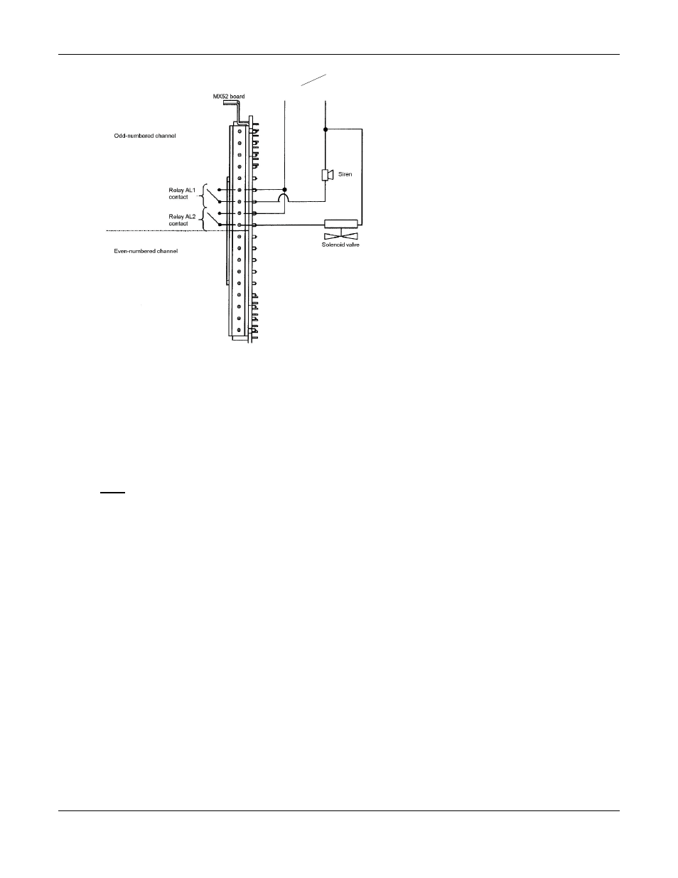
Figure 8: Example of External Device Connection
A siren connected to relay AL1 is actuated when alarm 1 is triggered,
A solenoid valve connected to relay AL2 is actuated when alarm 2 is triggered.
F
OR ALL
C
HANNELS
A common relay is associated with the triggering of alarm 3 for any and all of the 16 channels.
By programming, this common relay can also be used for the remote transmission of the audio warning signal. This
relay is then associated with all the control alarms. (See Figure 5)
A Fault relay associated with the triggering of channel faults (detector failures, electrical connections, excessively
negative zero, etc.). The Fault Relay is normally closed, it opens when in fault condition.
Common relay contact outputs are on the back of the power card: Figure 5.
N
OTE
:
The breaking capacity of the
MX52 C
ONTROL
relay contacts is 2 A / 250
V
AC
or 30
V
DC
, so external
intermediate relays must be used if the devices to be controlled require high current levels.
4.4.2 The 4-20mA Current Outputs
For each channel, the
MX52 C
ONTROL
is equipped with a 4-20 mA output that can be used to retransmit
sensor/transmitter outputs to a recorder, an external PLC or a computer. The maximum resistance in loop mode is 600
ohms. The ground connections for the 4-20 mA outputs are common. The 4-20 mA lines are not galvanically
insulated one from the other. The current output varies according to the situation and has several conditions other than
normal, as follows:
On starting up the unit: I < 1 mA
With FAULT: I < 1 mA
In MAINTENANCE mode: I = 2 mA
ZERO MEASUREMENT: I = 4 mA
Full scale: I = 20 mA
Out of range or “in doubt”: I > 23.2 mA
110V
AC
N
OTE
:
Auxiliary alarms should be powered from an independent
power source separate from instrument power to avoid
alarm failure due to controller malfunction.