ENMET MX-52 User Manual
Page 11
MX52 C
ONTROL
ENMET Corporation
7
4.2 Electrical Connections of the MX52 C
ONTROL
4.2.1 Power Supply
Voltage: 115
V
AC
(103 to 122 V) 50/60 Hz
Maximum power: 300 VA
Maximum current in cable: 1.5 A
Power wire, 3 conductors, 16g
Location of connection terminal blocks, see Figure 5
Protection: Overvoltage Clamp, 130 – 150% & Current Limit 130% typ, Self-Reset Foldback
Voltage: 207 to 244
V
AC
- 50/60 Hz on option
W
ARNING
:
Continuous gas detection and alarm systems (110
V
AC
/220
V
AC
/24
V
DC
/12
V
DC
powered) become
inoperative upon loss of primary power. Contact factory for specifications and pricing of backup
battery systems.
C
AUTION
:
It is mandatory that the instrument must be grounded to earth ground. This normally occurs through the ground
(green) wire of the AC power system. A terminal is also reserved for this purpose at the back of the power card,
see Figure 5. The ground connection is required in order to ensure correct operation of the following
•
Power interference filter
•
Protective devices against electromagnetic interference
4.2.2 DC Power supply
Voltage: 21 to 30
V
DC
Maximum power: 240 W
Maximum current in cable: 12.5 A
Cable: 2 x 14g
Location of terminal block, see Figure 5
Protection: Two fuses located at the back of the power card. See figure 5
4.3 Channel Board Connections
Each channel board includes terminal strips for each of two channels. The terminal strips for odd-numbered channels
are at the top, the terminal strips for even-numbered channels are at the bottom of each channel board. Figure 7 shows
these I/O terminal strips and identifies the positions on them.
4.3.1 Sensor/Transmitter
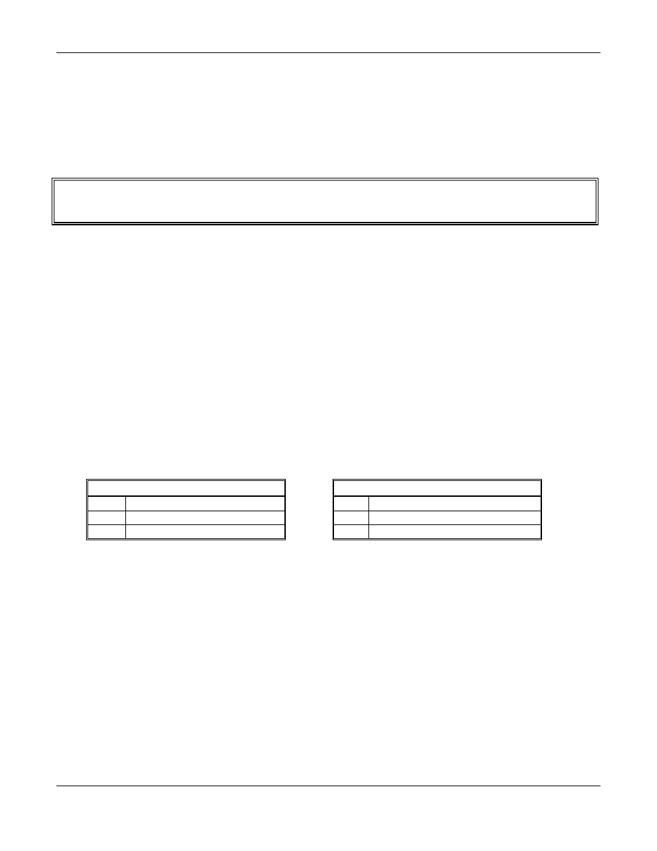
Sensor/Transmitters are connected to positions C1, C2 and C3 on each channel terminal strip. Connections are as follows:
Two Wire Sensor/Transmitter
Three wire Sensor/Transmitter
C1
Signal, minus
C1
Signal
C2
Not used
C2
Ground
C3
Signal, plus and +24V
DC
power
C3
+24V
DC
power
4.3.2 4-20mA Output Signal
The next two (+ 4-20mA –) positions in each terminal is the 4-20mA output from the
C
ONTROL
. The plus and minus
sides of the loop are indicated on the terminal strip.
4.3.3 Relay Contacts
MX52 C
ONTROL
relay contacts for the first two alarm levels are on the next four positions on the terminal strips, as
indicated in Figure 7. These relays have a maximum capacity of 2 Amp at 230 Volts, and are programmed as described
in Section 4.4.1. Open or closed contacts are selected with jumpers on the channel board as indicated in Figure7.
Figure 8 shows an example of external devices controlled by the
MX52 C
ONTROL
relay contacts.
The system alarm relay contacts AL3 are on the power supply board, as shown in Figure 5.
4.3.4 Wiring Requirements
Sensor/Transmitters
: Wiring to the sensor/transmitters should be by two or three wire shielded cable. The
recommended cable is 18 gauge three wire,
ENMET
part number 66017-006, Alpha-1747C or equivalent.
Output Loop
: Wiring to output loop should be similar two wire shielded cable.
Relay
: Relay wiring must be suitable insulated wire.