End view, Side view, 4 connecting the mx52 c – ENMET MX-52 User Manual
Page 12: Figure 7: channel board
ENMET Corporation
MX52 C
ONTROL
8
4.4 Connecting the MX52 C
ONTROL
to External Devices
4.4.1 Alarm Relays
The 16 channels of the
MX52 C
ONTROL
unit are each equipped with two relays that can be used to control external
devices such as sirens, solenoid valves, extractors, telephone callers, etc… Auxiliary alarms should be powered from
an independent power source separate from instrument power to avoid alarm failure due to controller malfunction.
An example of connection is given in Figure 8
F
OR EACH CHANNEL
:
The following relays are available (see Figure 7 and 12):
A relay associated with the triggering of alarm 1.
A relay associated with the triggering of alarm 2.
Use of open or closed contacts selected with a jumper (see Figure 7).
Use of positive or negative safety selected by programming (see the CHANNEL programming menu).
Contact outputs on the back of the two channel PCB (see Figure 12).
F
OR
S
YSTEM
R
ELAY
:
A relay associated with the triggering of alarm 3.
A relay associated with the triggering of a system fault.
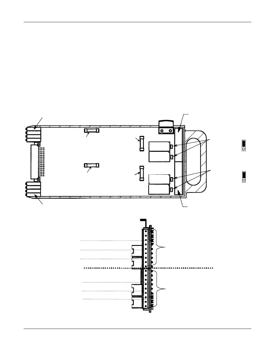
Figure 7: Channel Board
Output connector
Odd-numbered channel
See End view, below
Output connector
Even-numbered channel
See End View, below
Signal Fuse
Odd-numbered channel
Signal Fuse
Even-numbered channel
Line Fuse
Even-numbered channel
Line Fuse
Odd-numbered channel
Even-numbered channel
Jumpers
Open/closed contacts
Factory set NC
Odd-numbered channel
Jumpers
Open/closed
contacts
Factory set NC
Potentiometers
Odd-numbered channel
Potentiometers
Even-numbered channel
Relay Al1
odd channel
Relay Al2
odd channel
Relay Al1
even channel
Relay Al2
even channel
C1
C2
C3
+
–
RL
1
RL
2
C1
C2
C3
+
–
RL
1
RL
2
4-20mA
4-20mA
Output connector
Odd-numbered Channels
Output connector
Even-numbered Channels
Relay Alarm 1
Relay Alarm 2
Relay Alarm 1
Relay Alarm 2
End View
End View
End View
End View
Signal Fuse
Even-numbered channel
Signal Fuse
Even-numbered channel
Side View