Install components to pc board, Continue, Start here continue start here – Elenco Digital / Analog Trainer Kit Version User Manual
Page 9
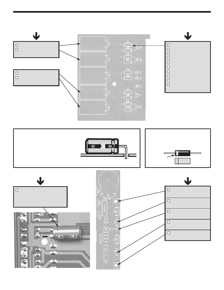
Figure I
Diodes have polarity. Mount them with
the band as shown on the top legend.
Figure J
These lytics must be mounted
horizontal to the PC board. Bend
the leads at right angles and then
insert the leads into the PC board
with the negative (–) lead and the
positive (+) lead in the correct holes
as marked on the PC board.
-8-
INSTALL COMPONENTS TO PC BOARD
C2 - 1000
µ
F 35V Lytic
C4 - 1000
µ
F 35V Lytic
(see Figure J)
Continue
L-Bracket
(see Figure B)
C7 - .1
µ
F Mylar (104)
(see Figure D)
J5 - Jumper Wire *
(see Figure F)
C9 - .1
µ
F (104) Mylar
(see Figure D)
L-Bracket
(see Figure B)
C1 - 1,000
µ
F 35V Lytic
C5 - 1,000
µ
F 35V Lytic
(see Figure J)
D1 - 1N4001 Diode
D2 - 1N4001 Diode
D3 - 1N4001 Diode
D4 - 1N4001 Diode
D5 - 1N4001 Diode
D6 - 1N4001 Diode
D7 - 1N4001 Diode
D8 - 1N4001 Diode
D9 - 1N4001 Diode
D10 - 1N4001 Diode
(see Figure I)
Bottom Right Corner of PC Board
C3 - 2200
µ
F Lytic
Mount on foil side of PC board
Note the polarity
(see Figure J)
Top Right Corner
of PC Board
* Leftover wire will be used in
future sections.
Band
+
Start Here
Continue
Start Here