Install components to pc board, Start here – Elenco Digital / Analog Trainer Kit Version User Manual
Page 8
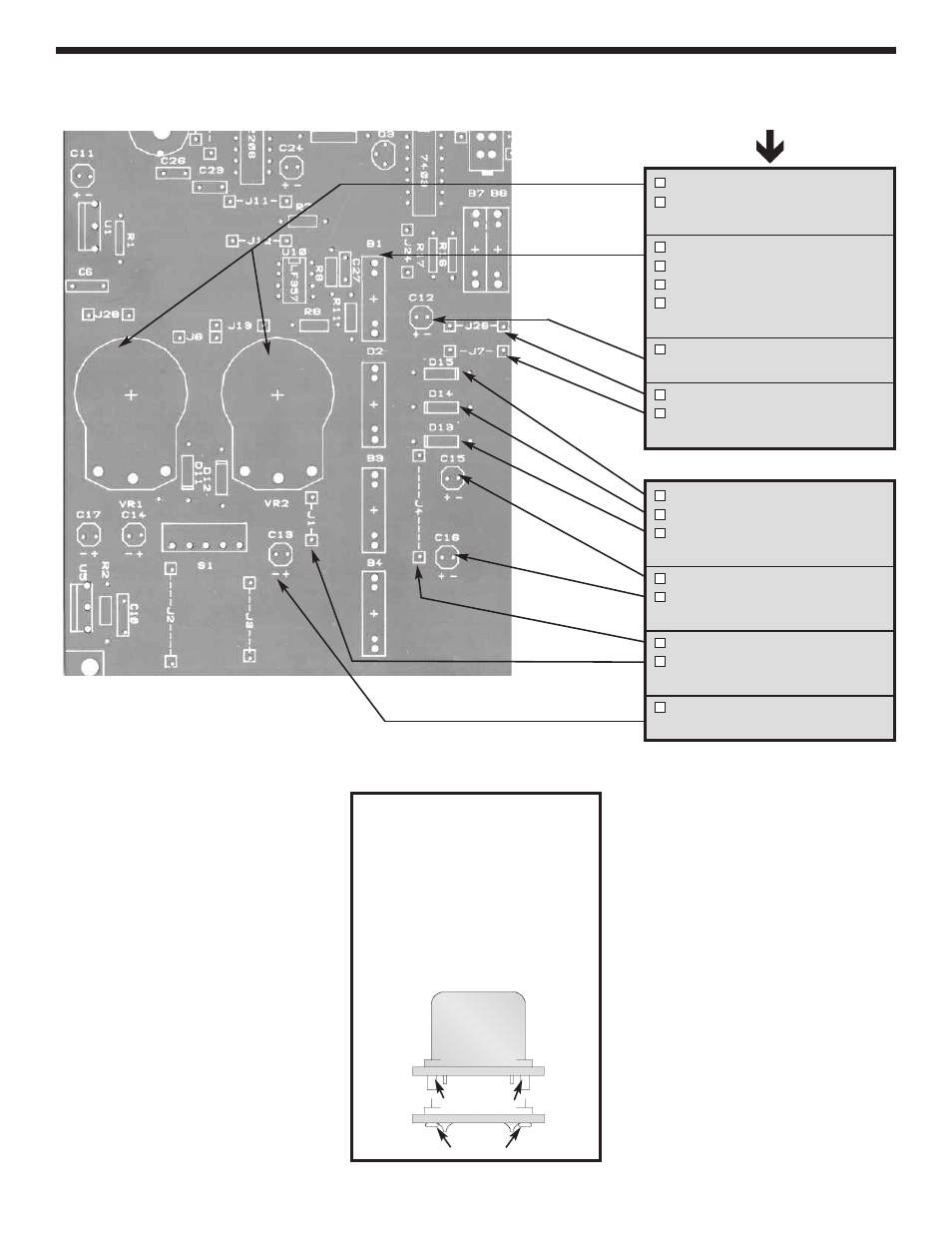
INSTALL COMPONENTS TO PC BOARD
VR1 - 2k
Ω
Pot
VR2 - 2k
Ω
Pot
(see Figure C)
B1 - 4-Pin Bredblox
B2 - 4-Pin Bredblox
B3 - 4-Pin Bredblox
B4 - 4-Pin Bredblox
(see Figure H)
C12 - 100
µ
F 25V Lytic
(see Figure E)
J26 - Jumper Wire
J7 - Jumper Wire
(see Figure F)
D15 - 1N4001 Diode
D14 - 1N4001 Diode
D13 - 1N4001 Diode
(see Figure G)
C15 - 100
µ
F 25V Lytic
C16 - 100
µ
F 25V Lytic
(see Figure E)
J4 - Jumper Wire
J1 - Jumper Wire
(see Figure F)
C13 - 100
µ
F 25V Lytic
(see Figure E)
Bottom Left Corner of PC Board
-7-
Figure H
Hold the bredblock down flush
to the PC board from the top
legend side and solder the
metal pins in place. Then, melt
the plastic pins with your
soldering iron to hold the
plastic blocks in place, as
shown.
Start Here
Plastic Pins
Melt Pins
See also other documents in the category Elenco Measuring instruments:
- SEE AMFM108CK (56 pages)
- Computer Inteface for Snap Circuits® (60 pages)
- Capacitor Substitution Box (8 pages)
- Diode/Transistor Tester Kit (12 pages)
- Diode/Transistor Tester (8 pages)
- Electronic Component Kit (28 pages)
- 100kHz Function Generator in Kit Form (16 pages)
- 100kHz Function Generator (8 pages)
- Surface Mount Generator Kit (16 pages)
- 5MHz Function Generator (12 pages)
- 015V Power Supply Kit (8 pages)
- Resistor Substitution Box (8 pages)
- 3 3/4 Digit Cap./Ind./Logic (2 pages)
- Logic Probe Kit (12 pages)
- Logic Pulser Kit (12 pages)
- Compact Digital Multimeter (20 pages)
- Digital Multimeter (18 pages)
- 3 1/2 Digit Cap. / Trans. Kit (36 pages)
- Compact Multimeter (8 pages)
- Digital Mulitmeter Kit (20 pages)
- 23 Range 20k/V VOM in Kit Form (20 pages)
- 3 1/2 Digit Cap./ Freq./ Trans. w/ Grey Boot (8 pages)
- 3 1/2 Digit with Temperature (36 pages)
- 3 1/2 Digit Cap./ Trans./ Freq (4 pages)
- Digital Bench Multimeter (26 pages)
- MicroMaster ® Computer Training Kit (116 pages)
- 100MHz Scope (68 pages)
- Wide Band RF Generator (7 pages)
- Deluxe Solar Educational Kit (15 pages)
- Soldering Station (20 pages)
- Soldering Station (4 pages)
- Soldering Station (6 pages)
- Surface Mount Technology Kit (12 pages)
- Practical Soldering Project Kit (16 pages)
- DataCom Tester Kit (28 pages)
- MultiModular Cable Tester (4 pages)
- Tone Generator (4 pages)
- Telephone Line Analyzer Kit (16 pages)
- Digital / Analog Trainer in Case (16 pages)
- Deluxe Digital / Analog Trainer with Tools Kit Version (52 pages)
- Digital / Analog Trainer (12 pages)
- Deluxe Digital / Analog Trainer (16 pages)
- Variable Voltage Power Supply Kit (12 pages)
- Variable Voltage Power Supply (8 pages)