Testing the function generator – Elenco Digital / Analog Trainer Kit Version User Manual
Page 33
VOLTAGE ANALYSIS OF ANALOG SECTION
Proceed with the voltage analysis only if the resistance readings were satisfactory. The values given below
are approximate.
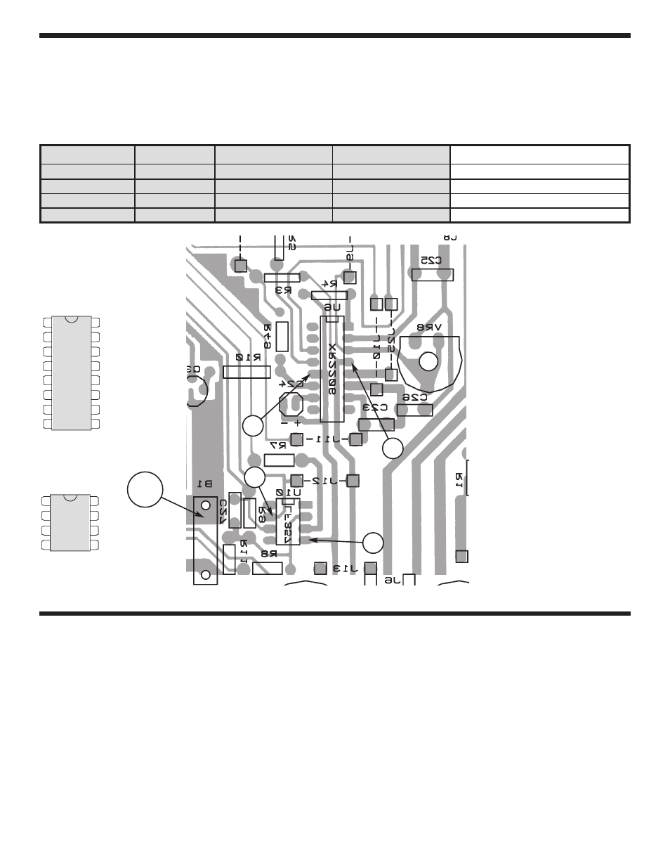
The following measurements will be taken from the copper side of the PC board. Turn the unit on and place it
upside down.
See Figure J for locations of the testing points.
From
To
Circuit
Volts
Volts Measured
Pin 4 (U6)
GND (B1)
U6 Vcc
+12V
Pin 12 (U6)
GND (B1)
U6 GND
–12V
Pin 7 (U10)
GND (B1)
U10 Vcc
+12V
Pin 4 (U10)
GND (B1)
U10 Vcc–
–12V
TESTING THE FUNCTION GENERATOR
Note: Use the knobs when turning the switches.
TESTING THE SINE WAVE
1. Set your meter to the 200mV DC range.
2. Connect the red meter lead to the 4-pin breadblock marked FREQ and the black lead wire to the 4-pin
breadblock marked GND.
3. Set the WAVEFORM knob to SINE, COARSE FREQUENCY knob to 1k and the FINE ADJ and AMPLITUDE
knobs fully clockwise.
4. Set the DC offset to the middle position. Then, turn on the trainer.
Turn unit right side up.
Figure J
-32-
1
2
3
4
5
6
7
8
10
9
11
12
13
14
15
16
1
2
3
4
8
7
6
5
U10
GND
U6
12
4
7
4
- SEE AMFM108CK (56 pages)
- Computer Inteface for Snap Circuits® (60 pages)
- Capacitor Substitution Box (8 pages)
- Diode/Transistor Tester Kit (12 pages)
- Diode/Transistor Tester (8 pages)
- Electronic Component Kit (28 pages)
- 100kHz Function Generator in Kit Form (16 pages)
- 100kHz Function Generator (8 pages)
- Surface Mount Generator Kit (16 pages)
- 5MHz Function Generator (12 pages)
- 015V Power Supply Kit (8 pages)
- Resistor Substitution Box (8 pages)
- 3 3/4 Digit Cap./Ind./Logic (2 pages)
- Logic Probe Kit (12 pages)
- Logic Pulser Kit (12 pages)
- Compact Digital Multimeter (20 pages)
- Digital Multimeter (18 pages)
- 3 1/2 Digit Cap. / Trans. Kit (36 pages)
- Compact Multimeter (8 pages)
- Digital Mulitmeter Kit (20 pages)
- 23 Range 20k/V VOM in Kit Form (20 pages)
- 3 1/2 Digit Cap./ Freq./ Trans. w/ Grey Boot (8 pages)
- 3 1/2 Digit with Temperature (36 pages)
- 3 1/2 Digit Cap./ Trans./ Freq (4 pages)
- Digital Bench Multimeter (26 pages)
- MicroMaster ® Computer Training Kit (116 pages)
- 100MHz Scope (68 pages)
- Wide Band RF Generator (7 pages)
- Deluxe Solar Educational Kit (15 pages)
- Soldering Station (20 pages)
- Soldering Station (4 pages)
- Soldering Station (6 pages)
- Surface Mount Technology Kit (12 pages)
- Practical Soldering Project Kit (16 pages)
- DataCom Tester Kit (28 pages)
- MultiModular Cable Tester (4 pages)
- Tone Generator (4 pages)
- Telephone Line Analyzer Kit (16 pages)
- Digital / Analog Trainer in Case (16 pages)
- Deluxe Digital / Analog Trainer with Tools Kit Version (52 pages)
- Digital / Analog Trainer (12 pages)
- Deluxe Digital / Analog Trainer (16 pages)
- Variable Voltage Power Supply Kit (12 pages)
- Variable Voltage Power Supply (8 pages)