Final assembly – Elenco Digital / Analog Trainer Kit Version User Manual
Page 21
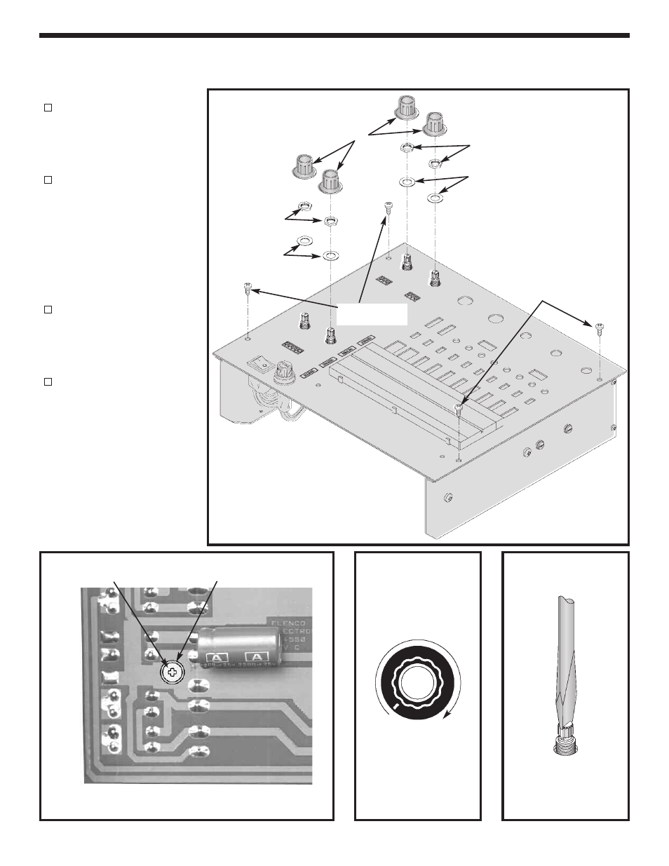
Figure Y
FINAL ASSEMBLY
If you are immediately going to build the remaining sections, do not continue with the instructions on
this page and proceed to page 22.
Fasten the front panel in
place with four #6 x 3/8”
thread cutting screws, as
shown in Figure W.
Fasten the PC board to the
spacer on the front panel
with a fiber washer and a
4-40 x 1/4” screw (from
Power
Supply
Section)
from the foil side of the PC
board,
in
the
location
shown in Figure X.
Fasten the pots to the front
panel with an 8mm washer
and a 7mm nut, as shown
in Figure W.
Turn the shafts on the two
switches
fully
counter-
clockwise. Push the knobs
onto the shafts so that the
line on the knob is in line with
the end of the circle on the
front panel (see Figure Y). If
the knob is loose on the
shaft, insert a screwdriver
into the slot and expand the
slot slightly (see Figure Z).
-20-
Figure X
4-40 x 1/4” Screw
Figure Z
Knobs
Nuts 7mm
Nuts 7mm
Washers 8mm
Washers 8mm
#6 x 3/8” Thread
Cutting Screws
#6 x 3/8” Thread
Cutting Screws
Figure W
Fiber Washer
- SEE AMFM108CK (56 pages)
- Computer Inteface for Snap Circuits® (60 pages)
- Capacitor Substitution Box (8 pages)
- Diode/Transistor Tester Kit (12 pages)
- Diode/Transistor Tester (8 pages)
- Electronic Component Kit (28 pages)
- 100kHz Function Generator in Kit Form (16 pages)
- 100kHz Function Generator (8 pages)
- Surface Mount Generator Kit (16 pages)
- 5MHz Function Generator (12 pages)
- 015V Power Supply Kit (8 pages)
- Resistor Substitution Box (8 pages)
- 3 3/4 Digit Cap./Ind./Logic (2 pages)
- Logic Probe Kit (12 pages)
- Logic Pulser Kit (12 pages)
- Compact Digital Multimeter (20 pages)
- Digital Multimeter (18 pages)
- 3 1/2 Digit Cap. / Trans. Kit (36 pages)
- Compact Multimeter (8 pages)
- Digital Mulitmeter Kit (20 pages)
- 23 Range 20k/V VOM in Kit Form (20 pages)
- 3 1/2 Digit Cap./ Freq./ Trans. w/ Grey Boot (8 pages)
- 3 1/2 Digit with Temperature (36 pages)
- 3 1/2 Digit Cap./ Trans./ Freq (4 pages)
- Digital Bench Multimeter (26 pages)
- MicroMaster ® Computer Training Kit (116 pages)
- 100MHz Scope (68 pages)
- Wide Band RF Generator (7 pages)
- Deluxe Solar Educational Kit (15 pages)
- Soldering Station (20 pages)
- Soldering Station (4 pages)
- Soldering Station (6 pages)
- Surface Mount Technology Kit (12 pages)
- Practical Soldering Project Kit (16 pages)
- DataCom Tester Kit (28 pages)
- MultiModular Cable Tester (4 pages)
- Tone Generator (4 pages)
- Telephone Line Analyzer Kit (16 pages)
- Digital / Analog Trainer in Case (16 pages)
- Deluxe Digital / Analog Trainer with Tools Kit Version (52 pages)
- Digital / Analog Trainer (12 pages)
- Deluxe Digital / Analog Trainer (16 pages)
- Variable Voltage Power Supply Kit (12 pages)
- Variable Voltage Power Supply (8 pages)