Right side, Wire the transformer to the pc board – Elenco Digital / Analog Trainer Kit Version User Manual
Page 12
-11-
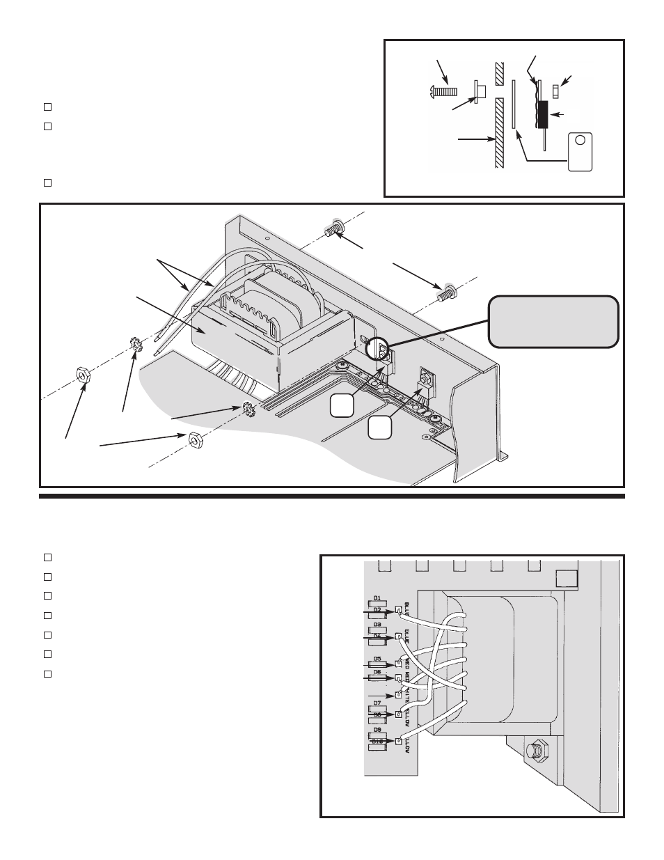
WIRE THE TRANSFORMER TO THE PC BOARD
Solder the wires to the PC board starting with the top yellow wire as shown in Figure P.
Yellow wire to point F on the PC board
Blue wire to point A on the PC board
Red wire to point C on the PC board
White wire to point E on the PC board
Red wire to point D on the PC board
Blue wire to point B on the PC board
Yellow wire to point G on the PC board
Mount U2 and U4 to the right side panel as shown in Figure O.
Insert the pins of each IC into the holes in the PC board. Then,
with the hardware shown in Figure MA, attach each IC to the
side panel. Solder the pins of the ICs to the PC board.
U4 - LM7912
U2 - LM7812
Mount the transformer with the black wires as shown in Figure O.
Use the two 8-32 x 3/8” screws, #8 lockwashers, and 8-32 nuts.
Transformer mounted
Right Side
Figure O
Note: Make sure that
the transformer does
not touch U4.
#8 Lockwashers
#8-32 x 3/8” Screws
8-32 Nuts
Transformer
Black Wires
U4
7912
U2
7812
Yellow (F)
Blue (A)
Red (C)
White (E)
Red (D)
Blue (B)
Yellow (G)
Figure P
Yellow (G)
Blue (B)
Blue (A)
Red (D)
White (E)
Yellow (F)
Red (C)
6-23 Nut
IC
* Silicone Grease
Side Panel
Insulator Washer
6-32 x 5/16” Screw
* Take a small amount of silicone grease from the packet and
apply it with a toothpick onto the back of the ICs.
Mica
Figure MA