Parts verification, Identifying resistor values, Identifying capacitor values – Elenco Digital / Analog Trainer Kit Version User Manual
Page 3
-2-
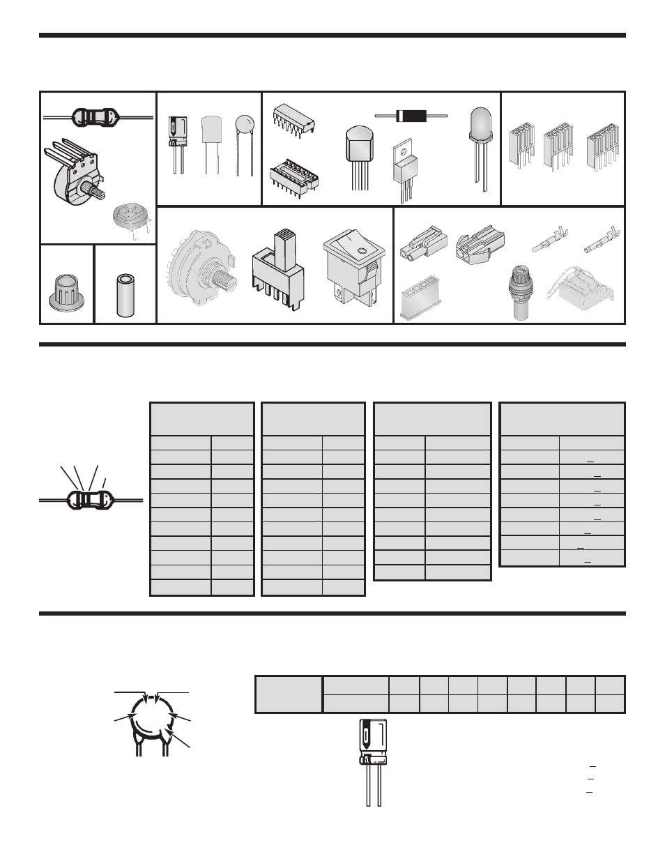
PARTS VERIFICATION
Before beginning the assembly process, first familiarize yourself with the components and this instruction book.
Verify that all parts are present. This is done best by checking off each item in the parts list.
IDENTIFYING RESISTOR VALUES
Use the following information as a guide in properly identifying the value of resistors.
BAND 1
1st Digit
Color
Digit
Black
0
Brown
1
Red
2
Orange
3
Yellow
4
Green
5
Blue
6
Violet
7
Gray
8
White
9
BAND 2
2nd Digit
Color
Digit
Black
0
Brown
1
Red
2
Orange
3
Yellow
4
Green
5
Blue
6
Violet
7
Gray
8
White
9
Multiplier
Color
Multiplier
Black
1
Brown
10
Red
100
Orange
1,000
Yellow
10,000
Green
100,000
Blue
1,000,000
Silver
0.01
Gold
0.1
Resistance
Tolerance
Color
Tolerance
Silver
+10%
Gold
+5%
Brown
+1%
Red
+2%
Orange
+3%
Green
+0.5%
Blue
+0.25%
Violet
+0.1%
Bands
1
2
Multiplier
Tolerance
Resistors
Capacitors
Electrolytic
(Lytic)
(Radial)
Connectors
Switches
Mylar
PC Mount
Potentiometer
Rotary
DPDT
Spacer
Discap
Knob
PC Mount
Trim Pot
3-Pin
4-Pin
5-Pin
Miscellaneous
Illuminated
Transformer
Bredblox
Connector Plug
Connector
Receptacle
Fuse
Assembly
Male Crimp
Terminal
Female Crimp
Terminal
Integrated
Circuit (IC)
IC Socket
Transistor
Integrated
Circuit (IC)
Diode
LED
IDENTIFYING CAPACITOR VALUES
Capacitors will be identified by their capacitance value in pF (picofarads), nF (nanofarads), or
µ
F (microfarads). Most
capacitors will have their actual value printed on them. Some capacitors may have their value printed in the following
manner. The maximum operating voltage may also be printed on the capacitor.
Second Digit
First Digit
Multiplier
Tolerance*
For the No.
0
1
2
3
4
5
8
9
Multiply By
1
10
100
1k
10k 100k .01
0.1
Multiplier
Note: The letter “R” may be used at times to
signify a decimal point; as in 3R3 = 3.3
1
0
µ
F
1
6
V
103K
100V
The letter M indicates a tolerance of +20%
The letter K indicates a tolerance of +10%
The letter J indicates a tolerance of +5%
Maximum Working Voltage
The value is 10 x 1,000 =
10,000pF or .01
µ
F 100V
*
Semiconductors