Caution – Elenco 3 1/2 Digit with Temperature User Manual
Page 25
Keep the following in mind while doing a continuity test:
• Even with the test leads shorted, the indicated value may not be
“0”. This is because of the resistance of the test leads and not a
fault. If necessary, you can press the REL
∆∆ button to
automatically subtract its value, then “0” will be indicated.
Measuring Capacitance
Caution
To avoid possible damage to the meter or to the equipment under
test, disconnect the circuit power and discharge all high-voltage
capacitors before measuring capacitance. Use the DC voltage
function to confirm that the capacitor is indeed discharged.
Capacitance is the ability of a component to store an electrical
charge. The unit of capacitance is the farad (F). Most capacitors
are in the nanofarad (nF) to microfarad (
µF) range.
The meter measures capacitance by charging the capacitor with a
known current for a known period of time according to the
measuring capacitance:
Measuring capacitance <4
µF
Measuring time is about 2 seconds
Measuring capacitance <40
µF
Measuring time is about 7 seconds
Measuring capacitance <100
µF
Measuring time is about 15 seconds
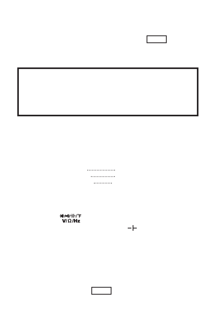
To measure capacitance, proceed as follows:
1. Turn on the meter, then set up the meter as shown in Figure 13.
2. Insert the black test lead into the COM terminal and the red test
lead into the terminal.
3. Set the Function Rotary Switch to the )
position (then, “AUTO”
and “nF” symbols are indicated on the display).
4. Connect the test leads to both ends of the capacitor under test,
then the measured value is shown on the display. If the capacitor
is polarized, connect the red test lead to the positive lead and
the black test lead to the negative lead.
The following are some tips for measuring capacitance:
• To improve the measurement accuracy of small value
capacitors, press the REL
∆∆ button with the test leads open
to subtract the residual capacitance of the meter and leads.
-25-