Connecting the usb interface – Echelon FT 5000 EVB User Manual
Page 25
FT 5000 EVB Hardware Guide
17
The following table lists the IO pins and IO devices associated with the jumpers on JP32.
Jumper
I/O Pin
IO Device/Functionality on FT 5000 EVB
1-2
IO6
SWSH (Shift register latch strobe for SW2 and Joystick)
3-4
IO7
TEMP (temperature sensor)
5-6
IO8
RXUSB (USB receive)
7-8 IO9 SW1
9-10 IO10 TXUSB
(USB
transmit)
11-12
IO3
PD (connects a 499 Ω pull-down resistor to IO3)
13-14
IO1
PD (connects a 499 Ω pull-down resistor to IO1)
15-16
IO9
PD (connects a 499 Ω pull-down resistor to IO9)
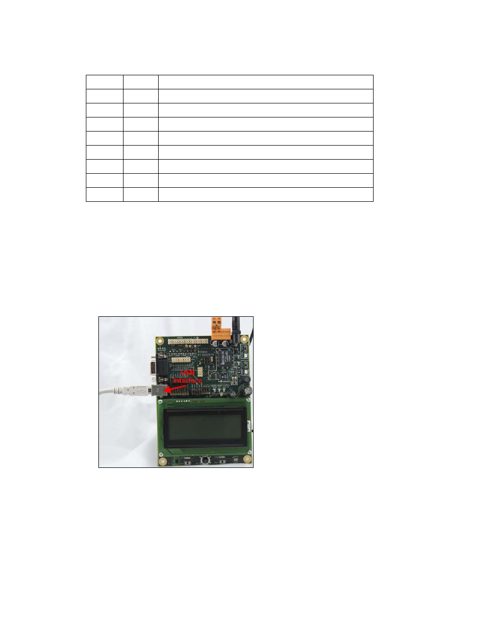
Connecting the USB Interface
You can enable serial communication without handshake lines and then connect your FT 5000 EVB to
your development computer via a USB interface. This lets you perform application-level debugging,
tests, or diagnosis. Once you create this USB connection, you can output debugging and tracing
information from the device application running on your FT 5000 EVB to a terminal emulation
program on your computer such as Windows HyperTerminal.
To create the USB connection for performing application-level debugging, follow these steps:
1. Connect the type A connector on a USB Type A to Type B Cable to an available USB port on
your computer, and then connect the type B connector to the USB interface on the left side of the
FT 5000 EVB.
2. Connect jumpers 5-6 (IO8 RXUSB) and 9-10 (IO10 TXUSB) on JP32. This connects the IO8 and
IO10 pins on the FT 5000 Smart Transceiver to the USB communications interface on the board.
IO10 is connected to pin 5 RXD as a serial data output to the USB interface, and IO8 is connected
to pin 1 TXD as a serial data input from the USB interface.