Cpd 3000 control sequence – Echelon Lumewave CPD 3000 Lighting Controller User Manual
Page 22
22
The CPD 3000 uses the nciPowerProfile table to define the expected power at
five equally spaced nviLampValue.values (.5%, 25%, 50%, 75%, 100%) once the
minPWM
and maxPWM CP fields have been established.
Note that nviLampValue.state is set to -1 at powerup/reset.
CPD 3000 Control Sequence
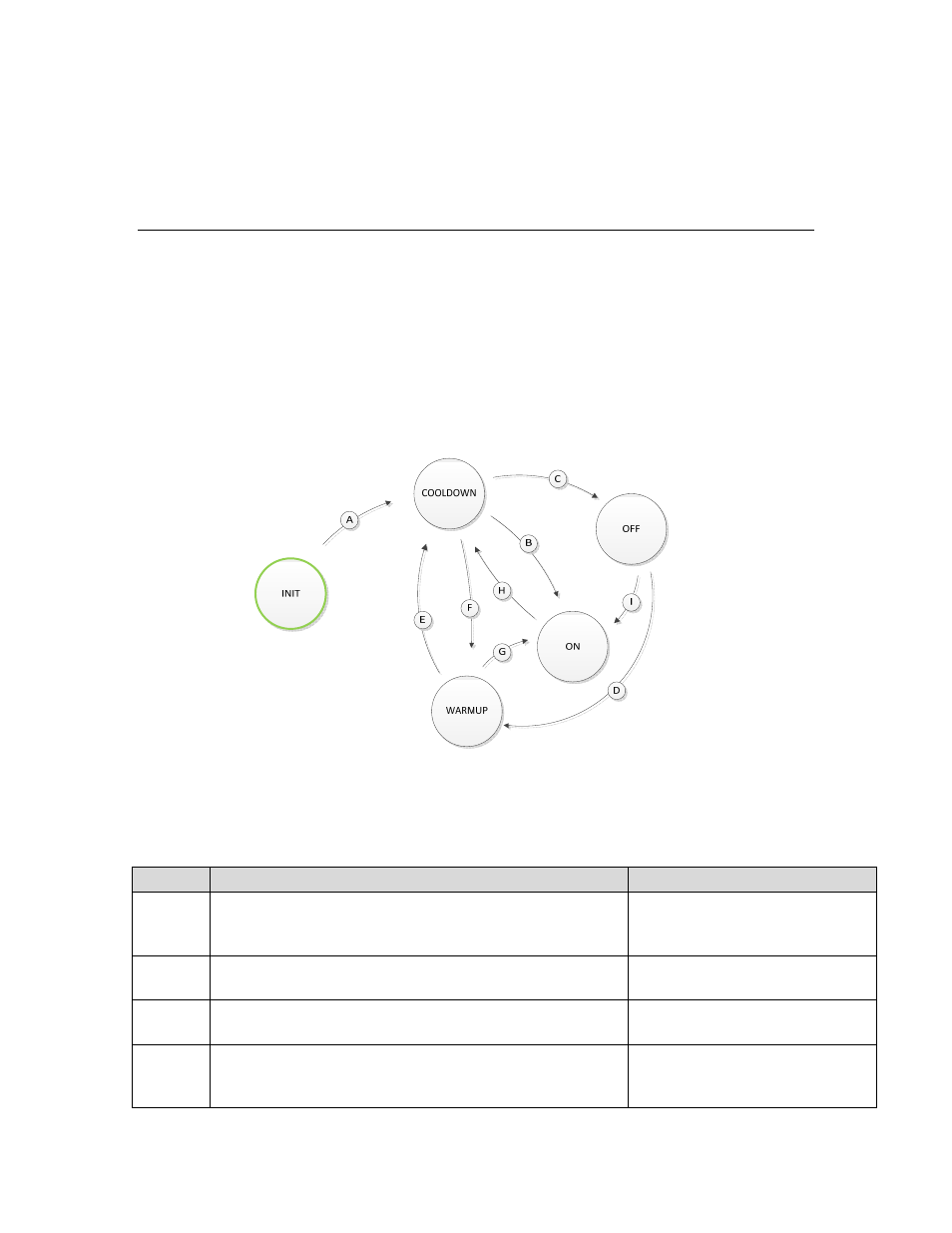
The CPD 3000 implements the state machine diagram depicted in figure 5 below.
The field nvoControData.LCstate reports the current active state for the
controller. To manage inrush current, the CPD 3000 uses an NTC Thermistor to
limit current inrush current commonly encountered with LED drivers and other
electronic ballasts. To be effective, the device needs a recovery time of 10s after
the load is switched ON. This means that power loss or reset will switch the load
OFF for 10s before turning the load ON. The configuration property field
nciControlCfg.cooldownTm
provides additional if required by the load under
control.
Figure 7. CPD 3000 State Diagram
Table 4. CPD 3000 Control State Transition Descriptions
Path
Condition
Comments
A Power-up
or
Reset
10s COOLDOWN minimum
enforced for inrush limiter
recovery.
B
COOLDOWN state timer expires AND (command ON
OR .defaultLev > 0)
An unconfigured node will
follow this path FULL_ON level
C
COOLDOWN state timer expires AND (.defaultLev ==
0 AND rcvTmo) OR command OFF
D
(Command ON OR (.defaultLev > 0 AND rcvTmo))
AND .warmup > 0
Warmup state always drives
the control signal to the
configured high limit.