Use and operation – Bullard T4MAXISE User Manual
Page 2
www.bullard.com
Figure 3
Use and Operation
This apparatus is suitable for use in Class I Zone 2 Group IIC
or unclassified or nonhazardous locations.
Power
To turn on your Bullard T4MAXISE Thermal Imager, depress and release the large, red power button
under the LCD display
(Figure 2). Upon pressing the power button the thermal imager will display the
Bullard logo and initiate a calibration sequence. The thermal image will appear within four seconds. To turn
off power, depress and hold the power button for three seconds and release.
NOTE
You will periodically observe a momentary freeze in the image. This is normal and is a function of
the self calibration shutter. The shutter will activate every 30 seconds to three minutes, depending
on the environment.
Low Sensitivity Mode
To maximize image performance, the T4MAXISE utilizes two modes. The standard mode, referred to
as high sensitivity mode, is the mode that is displayed when the unit is operating in normal or moderate
temperature environments. When the T4MAXISE displays hot scenes, typically fire scenes, it will switch to
the low sensitivity mode. This mode allows the unit to display a wider range of temperature but at lower
sensitivity within the scene. In this mode, certain details may be harder to distinguish.
Operation
Upon power on, the unit will display a grayscale thermal image. The battery indicator on the bottom center
of the display indicates remaining battery life. The battery indicator sections will deplete from left to right
as the battery drains. When only one section in the indicator remains, the T4MAXISE has approximately
30 minutes of battery life remaining. At 5 minutes remaining, the indicator will flash.
Relative Heat Indicator (RHI)
The T4MAXISE is equipped with temperature measurement capability in Basic Mode. The right side of the
display will show a bar graph or Relative Heat Indicator (RHI). as well as a numeric readout. The RHI will
indicate the approximate temperature of the object viewed within the temperature measurement zone
icon, the green square in the middle of the display. Additionally, a numeric temperature indicator below
the RHI bar will display the approximate temperature in a numeric value. The accuracy of the indicators
is dependent on numerous factors including the distance from the object being viewed and its emissivity,
which is the object’s ability to radiate heat. Units are calibrated with a preset emissivity corresponding
with normal construction materials. Objects with emissivities that vary greatly from this, such as metals
and shiny objects, will reduce the accuracy of the temperature indication. Additionally, temperature
measurement accuracy decreases as the distance from the object in the “crosshairs” increases.
NOTE
The RHI and numeric temperature indicator provide a quick reference to compare objects of
similar emissivities to serve as a guide to pinpoint intense heat sources. Due to the inherent issues
with accuracy, use this feature with caution and verify indicated heat levels through traditional
means whenever possible.
Super Red Hot Feature
The T4MAXISE features Super Red Hot high heat colorization. With the Super Red Hot feature, heat
levels are identified by various color hues. Starting at 500 degrees, heated objects are tinted yellow and
gradually transition to orange and then solid red as heat levels rise. The Super Red Hot feature identifies
specific heat layers alerting firefighters to areas of intense heat. This feature provides an enhanced visual
awareness of the hottest objects in a scene.
Electronic Thermal Throttle
®
The T4MAXISE incorporates a highly useful and unique feature, the Electronic Thermal Throttle. The
Thermal Throttle is ideal for pinpointing hot spots during overhaul, searching for overheated electrical
equipment, or clarifying objects in ambient temperature situations. To activate the Thermal Throttle option,
locate the two black buttons on the top of the T4MAXISE
(Figure 1). Press the down button (the button
closer to the front of the imager) to activate the Thermal Throttle. The Electronic Thermal Throttle will
automatically sense the hottest area in the scene and color it blue. Continuing to press the down button (or
holding it down) will further engage the Thermal Throttle and will color more of the scene blue, eventually
coloring even the coolest objects blue.
NOTE
As the throttle engages more of the scene, the blue will become lighter in hue to help differentiate
objects in the scene. As you cycle through the scene, you’ll see the symbol “TT” and a
corresponding number in the center left portion of the display. The “TT” indicates “Thermal
Throttle” mode. The number (0-100) is a point of reference to indicate the level of Thermal Throttle
engagement; by itself it has no specific meaning. To lessen the amount of blue in the scene, press
(or hold) the up button. Alternatively, pressing both buttons
simultaneously for one second will deactivate the Thermal
Throttle. A brief pressing of the power button deactivates
Electronic Thermal Throttle.
NOTE
The T4MAXISE Thermal Imager takes approximately eight
seconds to calibarate from initial startup. During this short
startup period, the Electronic Thermal Throttle or Digital
Zoom will not engage.
Digital Zoom Feature
The T4MAXISE enables magnification of far away scenes at both
2x and 4x zoom. With one push of the blue auxiliary button, the 2x zoom is
enabled
(Figure 2). A second push of the button activates the 4x zoom.
A third push of the button disables the zoom function. A “2X” or “4X” will
display in blue corresponding to the zoom level shown on the center left
portion of the display, when the zoom feature is activated. The Digital Zoom
feature also works seamlessly with Electronic Thermal Throttle and Super
Red Hot.
NOTE
The T4MAXISE Thermal Imager takes approximately eight seconds
to calibrate from initial startup. During this short startup period, the
Electronic Thermal Throttle or Digital Zoom will not engage.
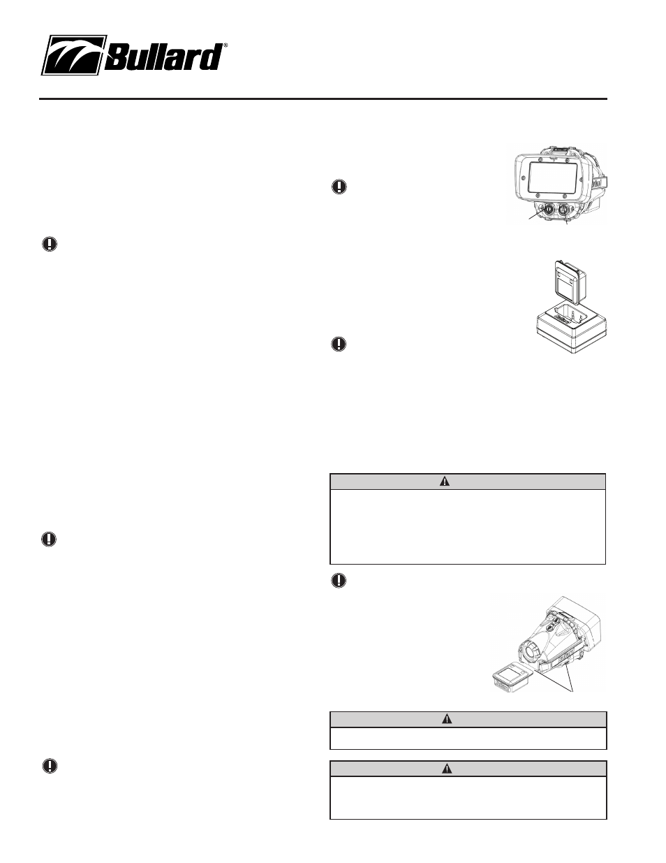
Using the Battery Charger
The battery should be charged in the battery charger using either the AC or DC adapter provided
(Figure 3).To charge a battery, insert it into the charger so that the metal contacts on the battery are
aligned with the metal contacts in the charger. A red light will illuminate on the charger to indicate that the
battery is charging. When the light on the charger turns to green, the battery is fully charged. You may
leave the battery in the charger indefinitely as the battery will not overcharge and the charger will initiate
a trickle charge to maintain the battery’s charge. For maximum battery life and performance, you should
remove the battery from the charger and discharge it completely on a monthly basis.
WARNING
EXPLOSION HAZARD
• Only use Bullard battery part number: NFPANIMH. Substitution of any other battery pack may
impair suitability for Zone 2.
• Do not charge battery packs in hazardous locations. Only charge using Bullard Desktop or
Powerhouse battery pack chargers.
• Do not insert or remove the battery pack unless the area is known to be free of ignitable
concentrations.
NOTE
If you do not see the red LED illuminate when you place a battery into the charger, the battery is
not charging.
Loading/Unloading the Battery
Loading and unloading the battery on the Bullard T4MAXISE
is straightforward
(Figure 4). To install a battery, ensure
the release buttons are unlocked, and slide the battery into
the groove on the bottom of the unit until an audible click is
heard, and the battery is firmly seated. To remove a battery,
depress both battery release buttons simultaneously and
slide the battery out of the unit. Since it can only be loaded
one way, the battery is easily replaced in the dark.
WARNING
Lock the battery release buttons before placing the imager in service. The imager shall not be used
in a hazardous location with the release buttons unlocked.
WARNING
Do not allow the metal contacts on the label side of the battery to come in contact with a conductive
surface, such as a metal table or another battery. This can complete the battery circuit and cause the
battery to overheat or melt. Failure to observe this warning may result in permanent battery damage,
property damage and/or serious injury.
Power Button
Zoom Button
Figure 2
Figure 4
Battery Locking Buttons