K. set step pulse type, L. step pulse noise filter – Bimba OLE User Manual
Page 16
k. Set step pulse type
Most indexers and motion controllers provide motion commands in the “Step
and Direction” format. The Step signal pulses once for each motor step and
the direction signal commands direction. However, a few PLCs use a differ-
ent type of command signal: one signal pulses once for each desired step in
the clockwise direction (called STEP CW), while a second signal pulses for
counterclockwise motion (STEP CCW). The drives can accept this type of
signal if you remove the cover and move jumper S3 from the “1-2” position to
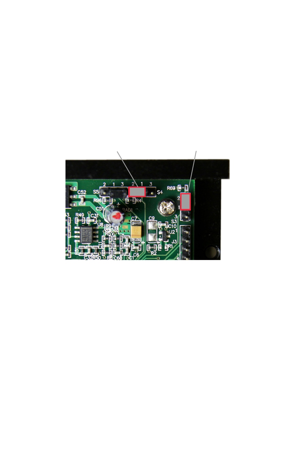
the “1-3” position. Factory default is the 1-2 position. As you can see in the
image, the jumper terminals (2, 1, 3) and S3 and S4 designators are printed
in white on the circuit board.
l. Step pulse noise filter
Electrical noise can cause the drive to think that one step pulse is two or
more pulses, resulting in extra motion and inaccurate motor and load posi-
tioning. To combat this problem, the drive includes a digital noise filter on the
STEP and DIR inputs. The default factory setting of this filter is 150 kHz.
If you are operating the drive at high speeds with step rates above 150 kHz,
remove the cover and move jumper S4 from the 150 kHz position (1-3) to the
2 MHz position (1-2) as shown below.
Your maximum pulse rate will be the highest motor speed times the steps/
rev. For example, 40 revs/second at 20,000 steps/rev is 40 x 20,000 = 800
kHz. Please consider this when deciding if you must increase the filter fre-
quency.
14
Jumper S4: noise filter
Shown in 1-2 position
Jumper S3: step pulse type
Shown in 1-2 position