3 clear cmos jumper, Clear cmos jumper, Table 1-9 – ADLINK iSeries Monitor 18/21 User Manual
Page 33: Lvds interface connector pin definition, Table 1-10
Introduction
21
TPZ-1300
Table 1-9: LVDS Interface Connector Pin Definition
1.7.3
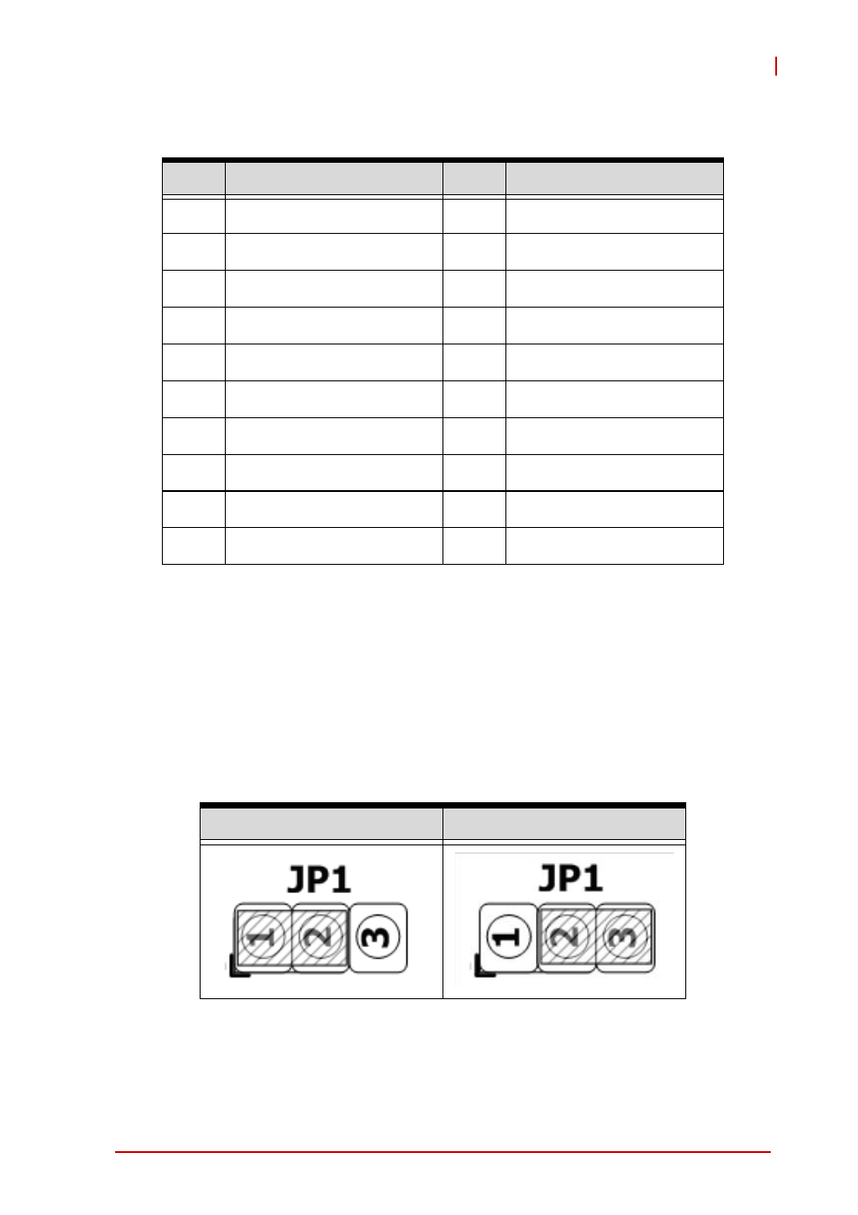
Clear CMOS Jumper
Upon encountering an abnormal condition preventing the
TPZ-1300 from booting, the jumper can clear the BIOS content
stored in CMOS and restore default settings. To clear CMOS,
short pin #2 to pin #3 of JP1 and then return to normal mode (short
pin #1 to pin #2).
Table 1-10: Clear CMOS Jumper
Pin
Signal
Pin
Signal
1
+LVDS_VCC
2
+LVDS_VCC
3
GND
4
GND
5
LVDS_CLK+
6
LVDS_TXP2
7
LVDS_CLK-
8
LVDS_TXN2
9
GND
10
GND
11
LVDS_TXP0
12
LVDS_TXP3
13
LVDS_TXN0
14
LVDS_TXN3
15
GND
16
GND
17
LVDS_TXP1
18
LVDS_DCLK
19
LVDS_TXN1
20
LVDS_DDAT
Normal
Clear