3 digital i/o connector, Digital i/o connector, Figure 1-10 – ADLINK iSeries Monitor 18/21 User Manual
Page 28: Di/o connector pin numbering, Table 1-6, D-sub 9p signal name of com1 & com2 ports
16
Introduction
Table 1-6: D-sub 9P signal name of COM1 & COM2 ports
1.6.3
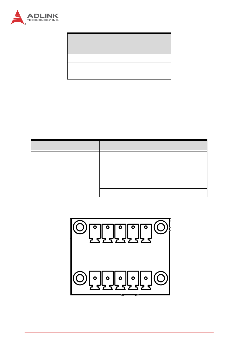
Digital I/O Connector
The TPZ-1300 provides four channel non-isolation digital input cir-
cuits and four digital non-isolation output circuits through a termi-
nal slot of pitch 3.81mm. Spec and connector pin numbering and
definitions are as follows.
Figure 1-10: DI/O Connector Pin Numbering
7
RTS#
N/S
N/S
8
CTS#
N/S
N/S
9
RI#
N/S
N/S
4-Channel Digital Input
4-Channel Digital Output
Logic high: 2 to 5.25 V
Output type: Open drain N-channel
MOSFET driver with internal pull high of
200
Ω
resistance
Output high: 2.4 to 5 V
Logic low: 0 to 0.8 V
Output low: 0 to 0.5 V
Source/Sink current for all channels: 24 mA
PIN
Signal name
RS-232
RS-422
RS-485
1
5
6
10