2 isolated digital output, Figure 2-2: common ground connection – ADLINK MXC-4000 Series User Manual
Page 26
16
System Description
2.3.2
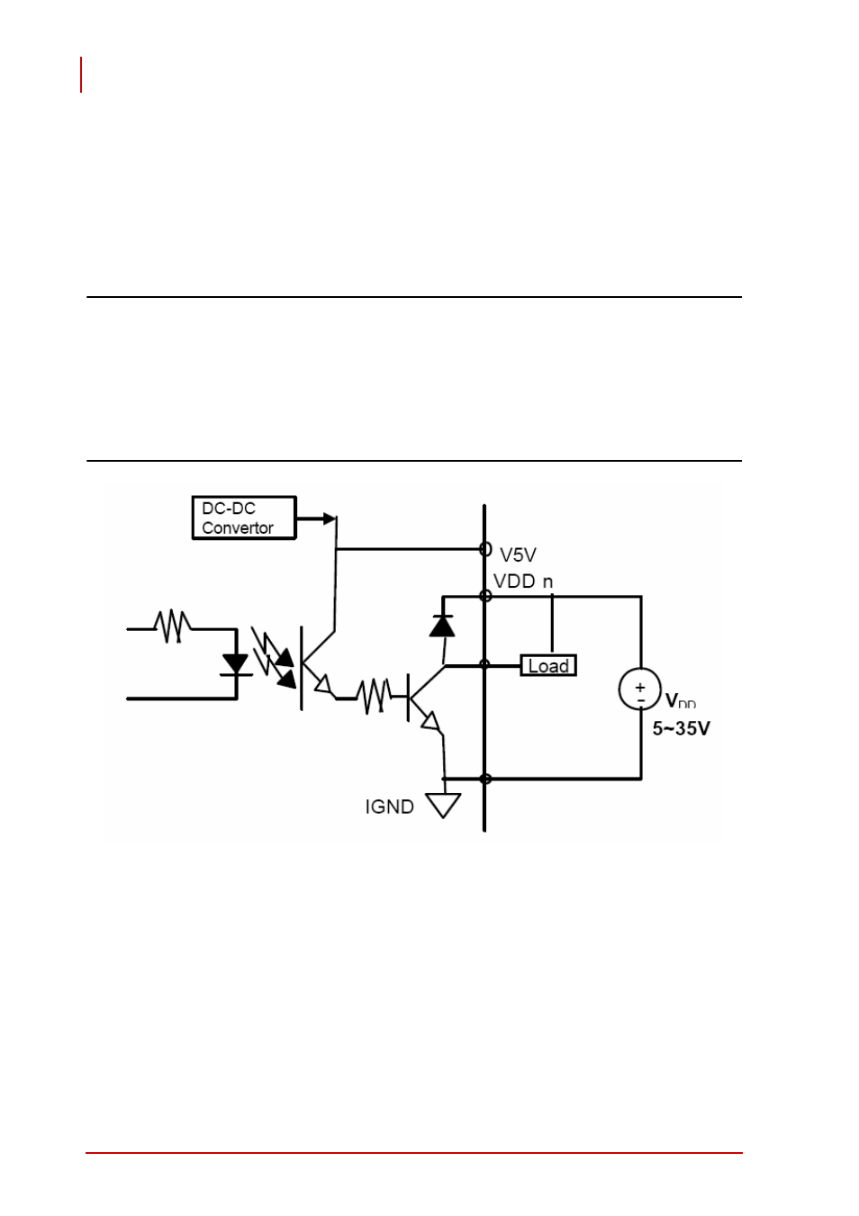
Isolated digital Output
Common ground connection of isolated digital output and common
power connection of isolated digital output are shown.
When isolated digital output enters an “ON” state, sink current is
conducted through the transistors. When an “OFF” state is
entered, there is no current through the transistors.
Note:
When the load is of an “inductance nature” such as a
relay, coil or motor, the VDD pin must be connected to an
external power source, with the extra connection utilized
for the ‘fly-wheel diode’ to form a current-release closed
loop, by which the transistors are protected from high
reverse voltage generated by the inductance load when
the output is switched from “ON” to “OFF”.
Figure 2-2: Common Ground Connection
- USB-1901 (84 pages)
- USB-1210 (54 pages)
- USB-2401 (60 pages)
- USB-7230 (50 pages)
- USB-2405 (56 pages)
- DAQe-2010 (92 pages)
- DAQe-2204 (100 pages)
- DAQe-2213 (94 pages)
- DAQe-2501 (74 pages)
- PXI-2010 (84 pages)
- PXI-2020 (60 pages)
- PXI-2501 (62 pages)
- cPCI-9116 (98 pages)
- ACL-8112 Series (94 pages)
- ACL-8112 Series (92 pages)
- ACL-8112 Series (93 pages)
- ACL-8216 (75 pages)
- ACL-8111 (61 pages)
- PCM-9112+ (10 pages)
- PCM-9112+ (94 pages)
- cPCI-6216V (47 pages)
- ACL-6126 (28 pages)
- ACL-6128A (40 pages)
- PCM-6308V+ (52 pages)
- PCM-6308V+ (4 pages)
- PCI-7444 (82 pages)
- PCI-7434 (48 pages)
- PCI-7234 (56 pages)
- PCI-7260 (66 pages)
- PCI-7258 (38 pages)
- PCI-7256 (48 pages)
- PCI-7250 (48 pages)
- LPCI-7250 (48 pages)
- PCI-7396 (65 pages)
- PCI-7296 (59 pages)
- PCI-8554 (67 pages)
- PCIe-7360 (94 pages)
- PCIe-7350 (86 pages)
- PCIe-7300A (114 pages)
- PCIe-7200 (51 pages)
- PCI-7300A (112 pages)
- PCI-7300A (83 pages)
- PCI-7200 (96 pages)
- cPCI-7300 (82 pages)
- cPCI-7300 (83 pages)