Signal connections & applications, 1 connectors pin assignment, 2 digital i/o connection – ADLINK cPCI-8554/R User Manual
Page 40
30 • Signal Connection and Applications
4
Signal Connections &
Applications
This chapter describes the connectors and applications of the cPCI/PCI-
8554/R including signal connections between the cPCI/PCI-8554/R and
external devices.
4.1
Connectors Pin Assignment
The cPCI/PCI-8554/R comes equipped with a 100-pin SCSI-II female
connector (CN1). CN1 is located at the rear plate. The pin assignment of
the connector is illustrated in the Figure 4 and 5 of section 2.1.
4.2
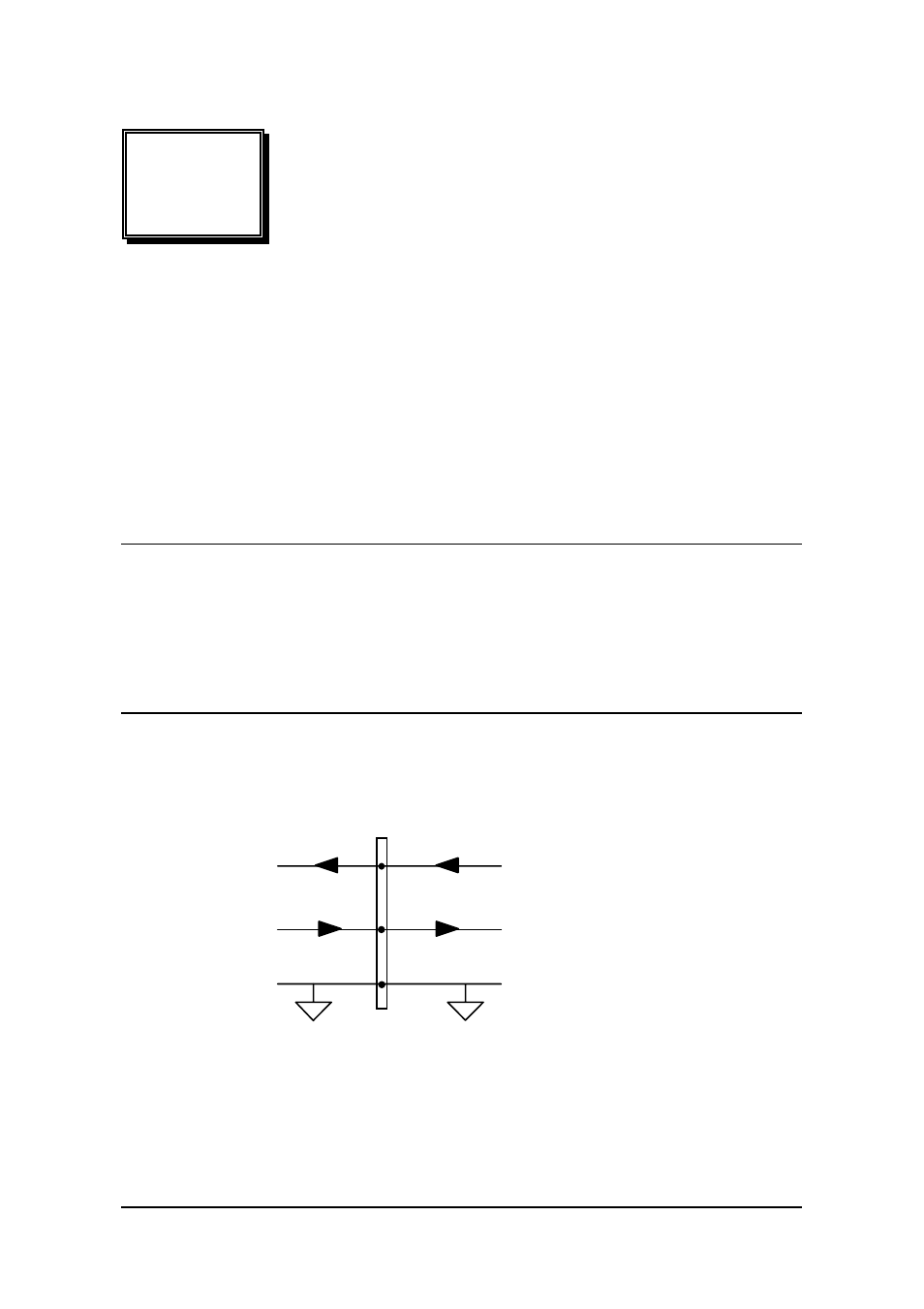
Digital I/O Connection
The cPCI/PCI-8554/R provides 8 digital input and 8 digital output channels
through CN1. The digital I/O signals are fully TTL compatible.
Digital Output (DO)
GND
Digital Input(DI)
From TTL Devices
To TTL Devices
ACL-8454
Outside Device
Figure 19: Digital I/O Connection
CPCI/PCI-8554/R