Daq/pxi-2005/2006/2016 ai data format, Mode (software polling), The daq/pxi-2005/2006/2016 – ADLINK PXI-2006 User Manual
Page 40: On the daq/pxi-2005/2006/2016
30
Operation Theory
DAQ/PXI-2005/2006/2016 AI Data Format
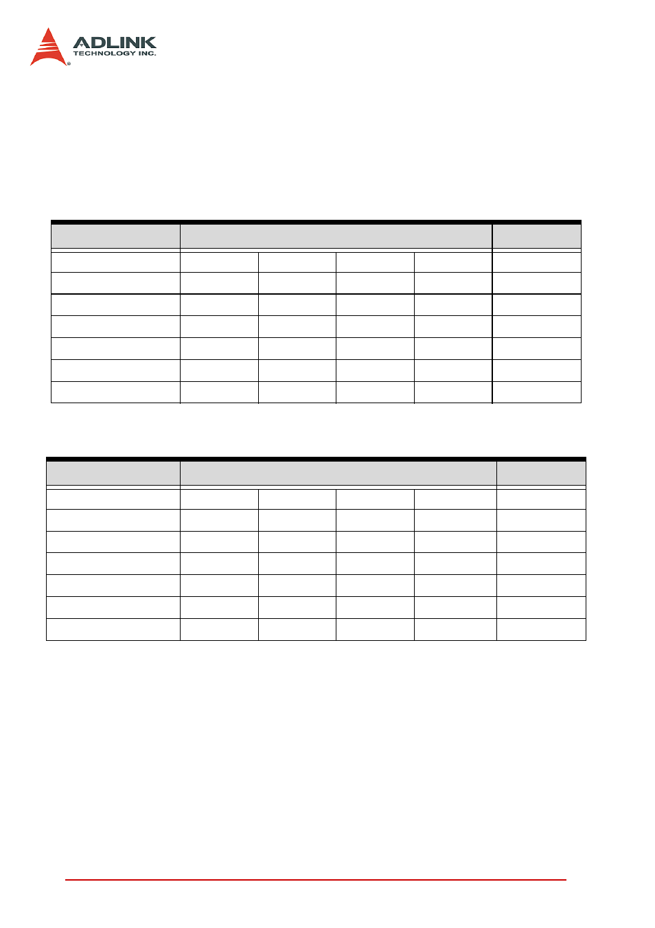
The data format of the acquired 16-bit A/D data is Binary coding.
Table 7 and 8 illustrate the valid input ranges and the ideal transfer
characteristics. The converted digital codes for DAQ/PXI-2005/
2006/2016 are 16-bit and direct binary, and here we present the
codes as hexadecimal numbers.
Software conversion with polling data transfer acqui-sition
mode (Software Polling)
This is the easiest way to acquire a single A/D data. The A/D con-
verter starts one conversion whenever the dedicated software
command is executed. Then the software would poll the conver-
sion status and read the A/D data back when it is available.
Description
Bipolar Analog Input Range
Digital code
Full-scale Range
±10V
±5V
±2.5V
±1.25V
Least significant bit
305.2uV
152.6uV
76.3uV
38.15uV
FSR-1LSB
9.999695V 4.999847V 2.499924V 1.249962V
FFFF
Midscale +1LSB
305.2uV
152.6uV
76.3uV
38.15uV
8001
Midscale 0V
0V
0V
0V
8000
Midscale -1LSB
-305.2uV
-152.6uV
-76.3uV
-38.15uV
7FFF
-FSR
-10V
-5V
-2.5V
-1.25V
0000
Table 4-3: Bipolar analog input range and the output digital code on the DAQ/
PXI-2005/2006/2016
Description
Unipolar Analog Input Range
Digital code
Full-scale Range
0V to 10V
0 to +5V
0 to +2.5V 0 to +1.25V
Least signifi-cant bit
152.6uV
76.3uV
38.15uV
19.07uV
FSR-1LSB
9.999847V 4.999924V 2.499962V 1.249981V
FFFF
Midscale +1LSB
5.000153V 2.500076V 1.250038V 0.625019V
8001
Midscale 5V
2.5V
1.25V
0.625V
8000
Midscale -1LSB
4.999847V 2.499924V 1.249962V 0.624981V
7FFF
-FSR
0V
0V
0V
0V
0000
Table 4-4: Unipolar analog input range and the output digital code on the DAQ/
PXI-2005/2006/2016