Rs485 bus termination, Om4000 jumper settings – Datalogic Scanning C-BOX 200 User Manual
Page 20
C-BOX 200
2
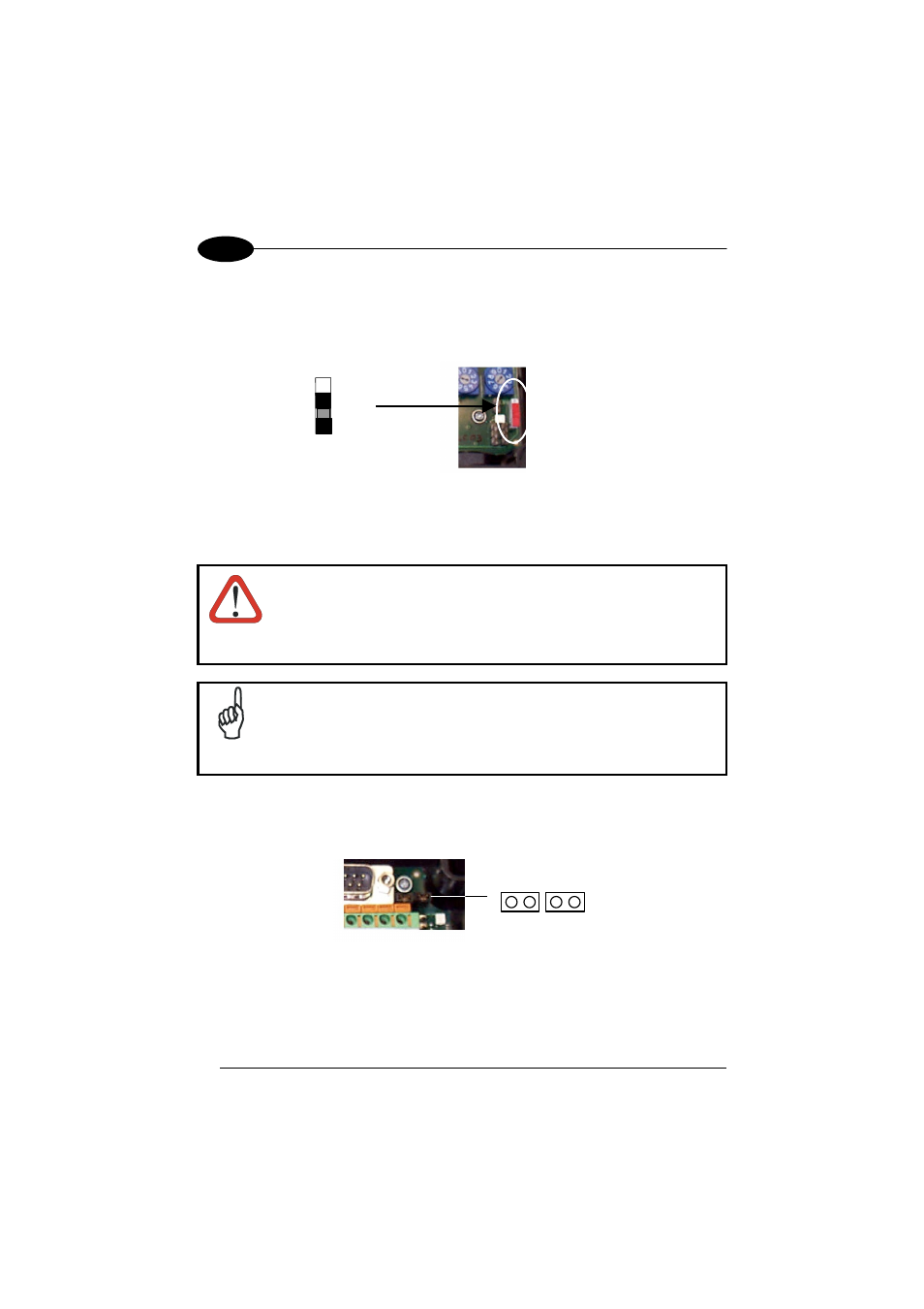
2.4.5 RS485
Bus
Termination
ON
OFF
Figure 12 - Termination Resistance Switch
This switch enables or disables the insertion of the bus termination resistor for RS485
Half Duplex Multidrop applications.
CAUTION
In Multiplexer applications the termination resistor must be enabled
ONLY on the last device of the chain, the farthest away from the
Multiplexer (assuming the Multiplexer is the first device of the
chain). On all the other devices this resistor MUST NOT be enabled
(OFF position).
NOTE
For all RS485 connections, in case of electrically noisy environments:
C-BOX 200 should be connected to a good earth ground (pin 7 or 8),
RS485 CABLE SHIELD should be connected to pin 7 or 8, the scanner
chassis should be connected to EARTH GROUND through the jumper,
see Figure 10.
2.4.6
OM4000 Jumper Settings
J1
J2
Figure 13 - OM4000 Jumpers
The jumpers allow connection to the EXT TRIG signals on separate spring clamp
terminals for applications which use the OM4000 Oscillating Mirror in Trigger Mode.
12