Delta transceiver, Recommended interface circuit (ac coupling) – Delta Electronics 1x9 Bi-Directional Transceiver Module OPBD-155F1J1R User Manual
Page 5
OPBD-155F1J1R
DELTA ELECTRONICS, INC.
5 Revision:
S2
03/09/2007
www.deltaww.com
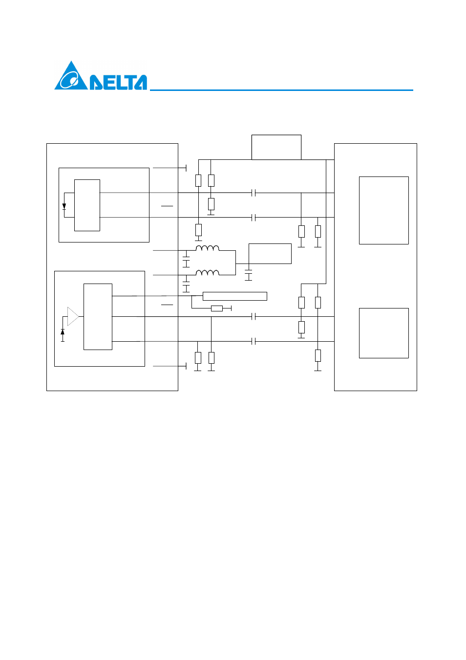
7. Recommended Interface Circuit (AC Coupling)
C1/2/3 = 4.7 uF
C4/5/6/7 = 100 nF
L1/2 = 1 uH
R1/2 =68
Ω (If C4/5=0, then R1/2 =82 Ω, it is for DC-coupled.)
R3/4 =180
Ω (If C4/5=0, then R3/4 =130 Ω, it is for DC-coupled.)
R7/8 =270
Ω
WR5/6/9/10/11/12 Depend on SerDes chip used
R13 = 510
Ω
Value of R5/6/9/10/11/12 may vary as long as proper 50
Ω termination or differential 100 Ω is
provided. For good EMI performance, the power supply filter is required. Use shorter tracks from the
inductor L1/2 to the module VccTx/VccRx .
Laser
Driver
LIMITING
Amplifier
Serializer/
Deserializer
ECL/PECL
DRIVER
Receiver
PLL etc.
VCC
TX+
TX-
RD-
RD+
VCC SerDes
3.3V
TXGND
TxD
TxD
VCCRx
VCC SerDes
3.3V
Pre-
Am p
SD
RxD
RxD
RxGND
VCCTx
Delta Transceiver
C2
C1
L2
L1
Signal detect
S D to upper leve l
R13
R1
2
R9
R1
0
R1
1
R6
R5
R3
R4
R2
R1
R7
R8
C3
C6
C7
C4
C5
1
2
3
4
5
6
7
8
9
5V
5V