Delta Electronics Ethernet Extension Module DOP User Manual
Instruction sheet
3
Please read this instruction carefully before use.
3
This instruction provides the information of specifications, installation and basic operation and settings.
Regarding the Ethernet Networking protocols supported by DOP-EXLNHJ1AE, there is no detailed
information available on this instruction. If the users need complete information of Ethernet Networking
protocols, please refer to relevant professional articles and books.
3
DOP series Extension Ethernet Module should be used with DOP-AE series HMI product. Ensure to
switch off the power before wiring.
3
Please install this DOP series Extension Ethernet Module in an enclosure free of airborne dust, humidity,
electric shock and vibration. The enclosure should prevent non-maintenance staff from operating the
device (e.g. key or specific tools are required for opening the enclosure) in case danger and damage on
the device may occur.
3
DO NOT touch any internal circuit in 1 minute after the power is switched off. Do NOT touch any
terminal when the power is switched on.
3
Make sure the ground terminal
is correctly grounded in order to prevent electromagnetic
interference.
3
DO NOT place any heavy objects on the connection port of DOP series Extension Ethernet Module.
Doing so may damage the product.
X
Introduction
1.1 Model
Explanation
DOP - EXLNHJ
1 AE
(1)
(2)
(3)
(4)
(1) Product Name
DOP: Delta Operation Panel
(2) Series
EXLNHJ: Extension Ethernet Module
(3) Version
(4) Applicable HMI Series
AE: DOP-AE Series HMI
1.2 Product
Outline
1. Connection Port for Ethernet
2. Direct Mounting Hole
3. Connection Port for Extension Module
4. Nameplate
Y
Function Specifications
Item
DOP-EXLNHJ1AE
Power Supply Voltage
DC 5V +/-10%, 1A (provided by HMI)
Interfaced Supported
RJ-45 with Auto MDI/MDIX
Number of Ports
1 Port
Transmission Method
(Standard Conformance)
IEEE 802.3, IEEE 802.3u
Transmission Cable
Category 5e (TIA/EIA-568-A, TIA/EIA-568-B)
Transmission Speed
10/100 Mbps Auto Detection
Ethernet Protocol
ICMP, IP, TCP, UDP, DHCP, Modbus TCP
Noise Immunity
ESD (IEC 61131-2, IEC 61000-4-2): 8KV Air Discharge
EFT (IEC 61131-2, IEC 61000-4-4): Power Line: 2KV, Communication I/O: 1KV
Damped-Oscillatory Wave: Power Line: 1KV, Digital I/O: 1KV
RS (IEC 61131-2, IEC 61000-4-3): 26MHz ~ 1GHz, 10V/m
Operation / Storage
Environment
Operation: 0
o
C~50
o
C (Temperature), 10%~85% (Humidity), Pollution Degree 2
Storage: -40
o
C~85
o
C (Temperature), 5%~85% (Humidity)
Vibration / Shock Resistance
Standards: IEC61131-2, IEC 68-2-6 / IEC61131-2 & IEC 68-2-27
Z
Installation & Wiring
3.1 Installtion
Wiring Note
1. Please avoid any conductive debris and tiny metal materials enter the Extension Ethernet Module when
screwing and wiring.
2. Allow a minimum space of 50mm between the Extension Ethernet Module and other control devices, and
keep the Extension Ethernet Module away from the high-voltage lines or any power equipment.
3.2 Caution
Environment
1. DO NOT install the Extension Ethernet Module in a place subjected to corrosive or flammable gases, liquids,
or airborne dust or metallic particles.
2. DO NOT install the Extension Ethernet Module in a location high temperature and high humidity (where
temperature and humidity will exceed specification).
3. DO NOT install the Extension Ethernet Module in a location where vibration and shock will exceed
specification.
[
Software Settings
Activate Delta Screen Editor software program. Under Application Name choose a name to save.
Under HMI choose a AE series HMI. Under Base Port Control choose Delta DVP TCP/IP.
Settings of DOP-EXLNHJ1AE
1. Select
Options > Configuration and click Communication tab. The users can choose Ethernet option
and set HMI IP address on right side of the window. If connecting to a DHCP Server, the users can select
DHCP to get network configuration automatically when the DHCP console starts. If Static IP address is
used, the users need to complete network configuration manually.
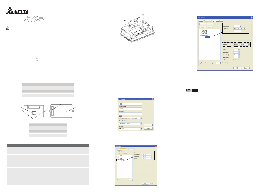
2. Clicking
Base Port option can set IP address of the connecting controller on right side of the window. If
the connecting controller is not Delta DVP series PLC, the users can change Delta DVP TCP/IP to
Modbus TCP/IP by using the Controller drop-down list.
3. After completing all settings, please click Ok button to save the settings and start to edit the screen data
of HMI.
NOTE
1) The content of this instruction sheet may be revised without prior notice. Please consult our distributors or download the most
updated version at http://www.delta.com.tw/industrialautomation.
http://www.delta.com.tw/industrialautomation/
Extension Ethernet Module
Instruction Sheet
Warning
1
3
4
2