Opep-33-a4q1r, Electrical interface characteristics, Transmitter burst mode timing characteristics – Delta Electronics GE-PON ONU Transceiver OPEP-33-A4Q1R User Manual
Page 4
OPEP-33-A4Q1R
DELTA ELECTRONICS, INC.
4 Revision:
S2
02/02/2007
www.deltaww.com
Note (1). Measured with Light source +1dBm, 1490nm, ER=9dB; BER =<10
-12
@PRBS=2
7
-1 NRZ
This assurance should be met with asynchronous data flowing out of the optical transmitter of
the system under test. The output data pattern from the transmitter of the system under test is a
repetition of alternate 0/1 pattern as defined for this measurement.
Note (2). When SD deasserted, the data output is Low-level (fixed)
Note (3). These are 20%~80% values.
Note (4). Measured at wavelength of 1490nm.
5. Electrical Interface Characteristics
Parameter
Symbol
Min.
Typ.
Max.
Unit
Note
Transmitter
Total Supply Current
I
CC
A
mA
Note
(1)
Differential line input Impedance
R
IN
80
100
120
Ohm
Differential Data Input Swing
V
DT
400 1600
mV
p-p
Data Input Voltage- High
V
IH
-V
CC
-1.165
-0.880
V
Data Input Voltage- Low
V
IL
-V
CC
-1.810
-1.475
V
LVPECL
BiasCNT Input Voltage- High
V
BCH
2 Vcc V
BiasCNT Input Voltage- Low
V
BCL
0 0.8 V
LVTTL
Receiver
Total Supply Current
I
CC
B
mA
Note
(1)
Differential Data Output Swing
V
DR
400
650
900
mV
p-p
Note
(2)
Signal Detect Output Voltage-High
V
LOSH
2
Vcc+0.3
V
Signal Detect Output Voltage-Low
V
LOSL
0 0.8 V
LVTTL
Note (1). A (TX)+ B (RX) = 300mA (Not include termination circuit)
Note (2). Internally AC coupled, but requires a 100Ohm differential termination at or internal to Serializer/
Deserializer.
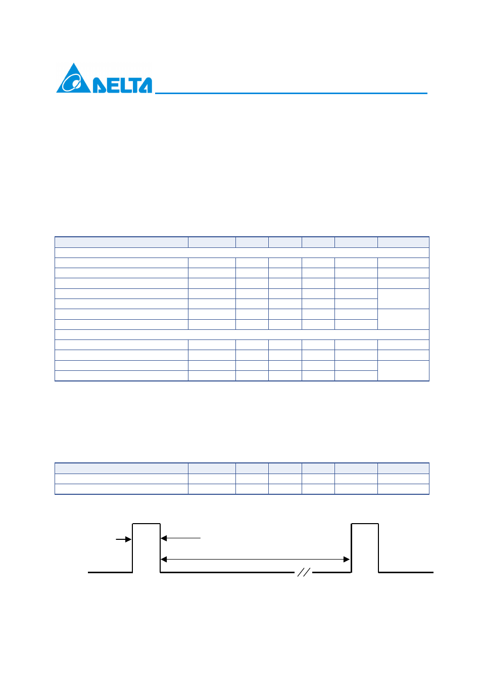
6. Transmitter Burst Mode Timing Characteristics
Parameter
Symbol
Min.
Typ.
Max.
Unit
Note
BiasCNT Enable Duration
1
us
Interval of BiasCNT Signal
0.112
1000000
us
BiasCNT
Interval of BiasCNT Signal
BiasCNT Enable Duration