Wiring diagrams – Aiphone NEM-30/C User Manual
Page 7
Attention! The text in this document has been recognized automatically. To view the original document, you can use the "Original mode".
5
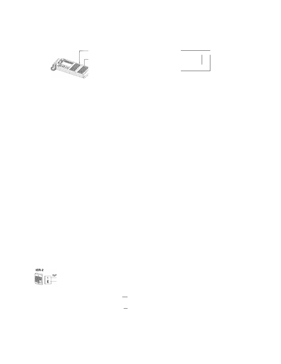
WIRING DIAGRAMS
Basic master to sub system
Master station
Sub stations
t common + no. of subs
1 common + no. of subs
2 - f
4
iji]
■V ■■■
NA-AN
NA-NE
Sub stations
NEM-40A/C
S
m
■Ji
4
Red —'
Orange
Org/whit
Blue
Green
Black -
At ail NA sub stations, link or jumper remain attached.
■fill
A
B
C
D
ill
il
ll
Red-^
Orange
Org/whit
Blue
Green
Black —
@
Do not connect two power
supplies in parallel.
NOTES
1. Wiring: 2 wires per sub (in same jacketed cable)
2. Terminai E (max. 10) may be used for one to max. 3 wiring biocks.
3. Cali extension: One IER-2 per NEM
4.
Any NA sub station may remain equipped with a link or jumper wire.
ISSl : PS-2410A, PS-24ME(forupto20subs).
PS-24E (for 1 ~ 40 subs).
/j\ To avoid noise interference, be sure to take G terminal on
PS-24E to earth.
7 -