Wiring required, Actual tb-f terminal locations, Installation for wall mounting – Aiphone TB-3F User Manual
Page 3: Installation of terminal box
Attention! The text in this document has been recognized automatically. To view the original document, you can use the "Original mode".
WIRING REQUIRED
TB-l F: 5 Conductors maximum
TB-3F: 8 Conductors maximum
TB-6F:
11 Conductors maximum
TB-12F; 17 Conductors maximum
Refer to the chart below and select the proper wire gauge to meet your requirements.
AWG WIRE SIZE
24 AWG
22 AWG
20 AWG
MAXIMUM COMMUNICATION DISTANCE
BETWEEN MOST DISTANT PHONES
1200'
2000'
3000'
MAXIMUM COMMUNICATION DISTANCE
FROM PHONE TO DOORS STATION
300'
500'
700'
DIAMETER OF WIRE
0.5 mm
0.65 mm
0.8 mm
MAXIMUM COMMUNICATION DISTANCE
BETWEEN MOST DISTANT PHONES
400 m
650 m
1000 m
MAXIMUM COMMUNICATION DISTANCE
FROM PHONE TO DOOR STATION
90 m
150 m
230 m
Begin your installation with station #1. A space is provided at the left of the diagram to write in your color code. Note
the position of the C terminal at each station. Be sure you wire each station correctly.
After installing your second station we recommend that the power supply be connected to the ©and ©terminal lines at a
convenient location and that a test be made for calling and talking between each station. As each additional station is install
ed re-test between each station. Unplug power supply while making wiring connections.
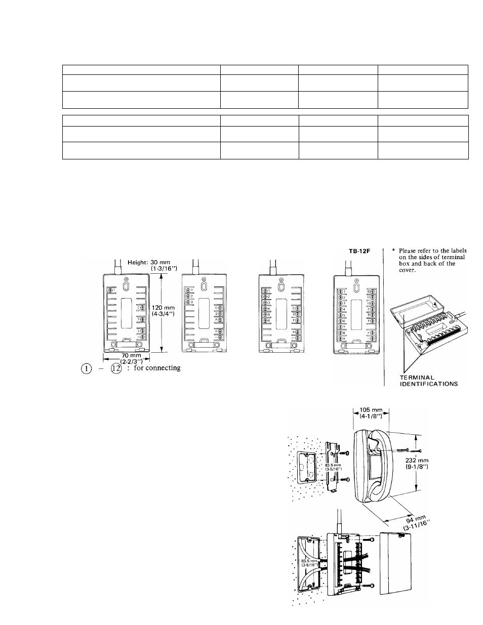
ACTUAL TB-F TERMINAL LOCATIONS
TB-1F
TB-3F
TB-6F
©
©
o
for receiving call and talking
for connecting door station
for both door station and paging
for power supply
INSTALLATION FOR WALL MOUNTING
1) Attach the mounting bracket to wall or
single gang plaster ring.
2) Attach handset cradle included, as shown
in illustration.
NOTE: Terminal cord may be pulled out
from either the top or the bottom
of the body, or straight back to
plaster ring.
INSTALLATION OF TERMINAL BOX
(Can be mounted easily to wall or single gang
box.)
1) Remove screws and cover as shown.
2) Attach bottom case to wall or 1-gang box.
3) Replace cover after wiring.
-
3