System layout, Components available, Actual terminal location – Aiphone IC-1AD(U) User Manual
Page 2
Attention! The text in this document has been recognized automatically. To view the original document, you can use the "Original mode".
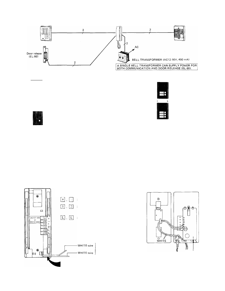
SYSTEM LAYOUT
Door station
Room station
Call extension
COMPONENTS AVAILABLE
* Door stations: Select either type from the 1C series door stations;
1
IC-DC: w/plastic cover.
Surface-mount.
IC-NA: w/plastic cover.
Semi-flush mount.
IC-RA: w/brown metal cover.
Semi-flush mount.
IC-KA; w/brown metal cover.
Semi-flush mount.
e
IC-JA: w/stainless steel cover.
Flush-mount.
IC-FY: w/aluminum cover.
Flush-mount.
IC-D2, -DL2
IC-D1,IC-DL1; 1-call.
IC-D2, IC-DL2: 2-call.
IC-D3,IC-DL3; 3-call.
w/anodized aluminum cover.
Surface-mount.
(IC-DL
type: with illumina-
IC-D3, -DL3 tion lamp)
IC-DA-R; w/plastic cover.
Surface-mount.
Options;
■
ICR-1: Call extension.
Announces a call from door by
chime in a place remote from
IC-IAD(U) (one per system).
EL-9S: Electric door release.
AC 12 V, 250mA. May be
powered by a system’s bell
transformer (one per system).
NOTES:
Your lC-1 AD(U) unit can also work with the existing models; IB-DA, IB-NA, IB-RA, IB-RAG, IB-JA, IB-FY and IBR-l/A.
ACTUAL TERMINAL LOCATION
IC-1AD(U)BACK VIEW
For power supply.
Connect to QH , [
2
] terminals
on door station (non-polarized)
Connect to electric door release
(non-polarized)
CASE & CHASSIS
For call extension
(non-polarized)
(1) Remove 2 screws on back of the chassis and separate front case and chassis.
(2) As shown, take out two WHITE wires thru a hole on the chassis.
(3) Connect 2 wires to the wires from the ICR-1 (non-polarized).
INSIDE VIEW
PC BOARD