Actual terminal location, Installation – Aiphone HOME INTERCOM LAF-7B User Manual
Page 3
Attention! The text in this document has been recognized automatically. To view the original document, you can use the "Original mode".
*Volume adjustment;
LAF-B unit has pre-setting volume, allowing to lower the maxumum level of
communication. On back of LAF-B unit, using a philip screwdriver, turn the
volume counter-clockwise to achieve the desired level.
On front panel, LAF-B unit has two volume controls for communication and call
tone, each adjustable to three levels as desired.
COMMUNICATION VOLUME
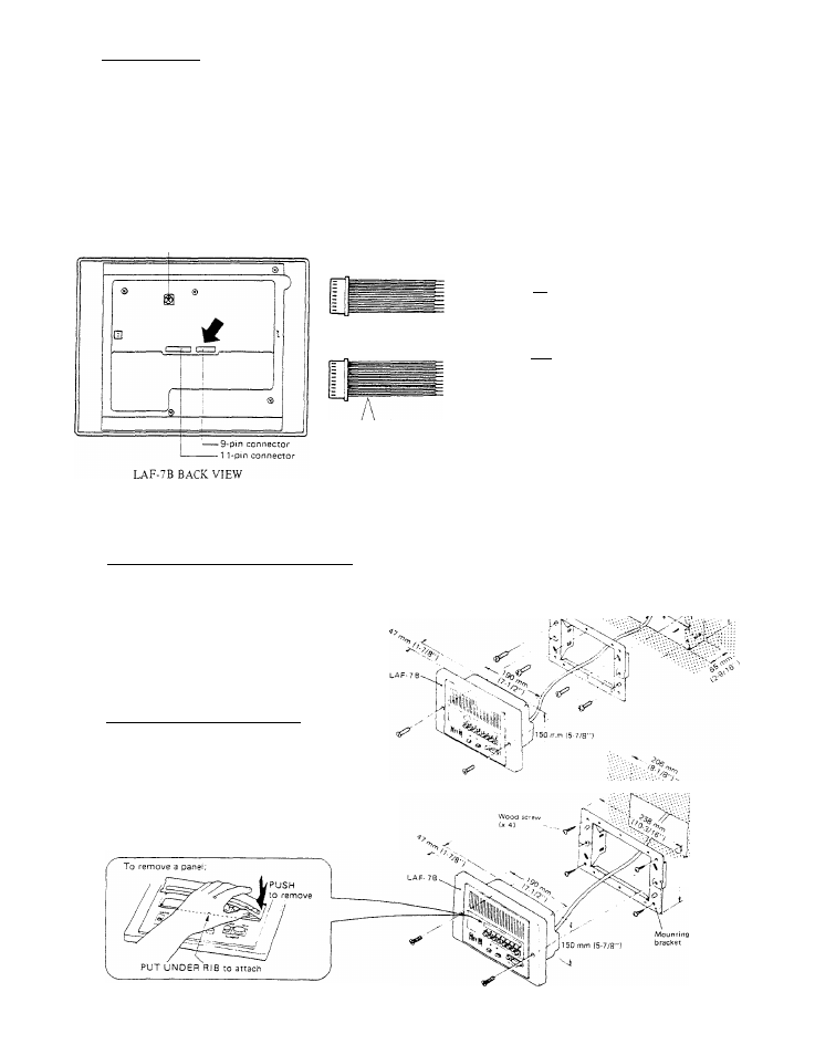
LAF-78 BACK VIEW
ACTUAL TERMINAL LOCATION
Max. communication pre-set
volume control
9-pin connector with 7 -
wires of approx.
22
cm
(8-5/8”)
1 Tpin connector with -
10
wires of approx.
22
cm
(8-5/8”)
s
s
CD
- I'Ti for
connecting station unitjTI ~ [T]
for receiving a call and BGM
(~7 for power supply
for common communication
for occupied lamp
for .All Call control
fPTi for All Call output
for sub call-in tone during
communication
for door release control
PIN/WIRE COLOR CODE
1. Brown
5.Green
2
. Red
6
.Blue
3.Orange
7.Purple
4.Yellow
8
.
—
NDENTlFiCATlON
9. -
10
. -
C. Brown
£. Orange
Y. Yellow
Pj . Green
P;. Blue
P
3
. Purple
R. Gray
L. White
+ . Red
—. Black
3
INSTALLATION
(1) Semi-flush mounting to wall (in new construction);
For new construction, use a mounting back
box (Model: BBX-1).
1. Install the back bo.x in the wall.
2. Attach the supplied mounting bracket with
four screws (supplied).
3. Mount LAF-7B unit to the bracket with two
screws (supplied).
(2) Semi-flush mounting to an existing wall;
1. To install LAF-"?B unit to an existing
wall, cut and open a hole of H: 165 mm
(6-1/2") X W: 206 mm (8-1/8"), securing
depth of more than 47 mm (1-7/8"),
2. Attach the mounting brocket directly to
wall with four wood screws (supplied),
3. Mount LAF-7B unit to the bracket with
two screws (supplied).
Mounting
aack
box
(BBX-1)
ra'-.
>-
.'•'•.■.•'•,1 65 mm
1 92 mm j
|7-9/16"1 '■•••
-
3