User interface, 10 user interface, Rs232 pc-side connections – Datalogic Scanning Compact 2D Reader Matrix-2000 User Manual
Page 67: Pin connector electrical connections
19-PIN CONNECTOR ELECTRICAL CONNECTIONS
5
5.10 USER INTERFACE
RS232 PC-side connections
1
5
9
6
9-pin male connector
13
25
14
1
25-pin male connector
Pin Name
Pin
Name
2 RX
3
RX
3 TX
2
TX
5 GND
7
GND
7 RTS
4
RTS
8 CTS
5
CTS
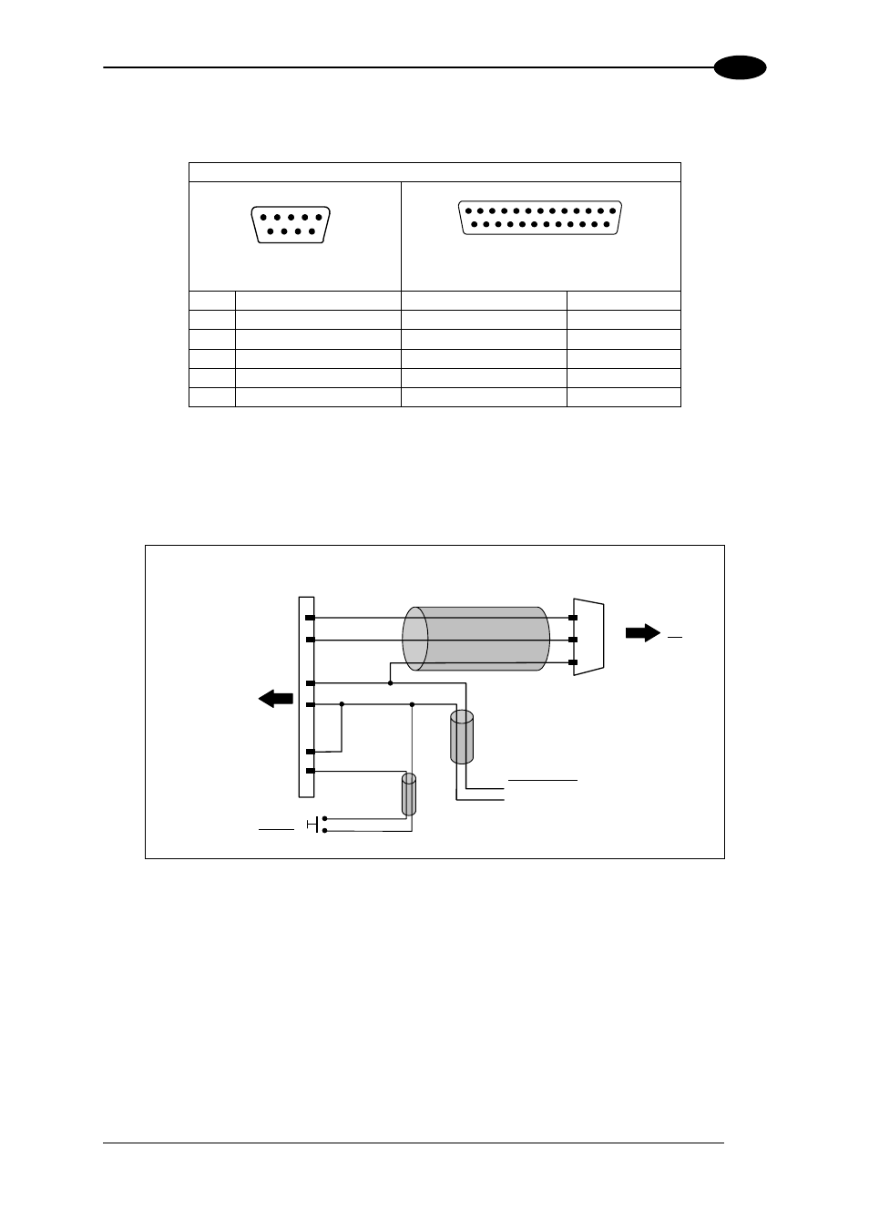
How To Build A Simple Interface Test Cable:
The following wiring diagram shows a simple test cable including power, external (push-
button) trigger and PC RS232 COM port connections.
DB25-pin female
20
RX
TX
21
Matrix-2000™
13
25
Vdc
GND
9-pin D-sub female
GND
TX
RX
PC
2
3
5
18
I1A
Power Supply
Power GND
VS (10 – 30 VDC)
Trigger
I1B
19
Figure 86- Test Cable for Matrix-2000™
57