External lighting systems, 6 external lighting systems – Datalogic Scanning Compact 2D Reader Matrix-2000 User Manual
Page 51
CBX ELECTRICAL CONNECTIONS
4
4.6 EXTERNAL LIGHTING SYSTEMS
If an External Illuminator is used, it can be powered from the CBX connection box. It must be
connected to the Vdc and GND terminal clamps.
CAUTION
Power is available directly to the Illuminator, independently from the Power
Supply Switch inside the CBX.
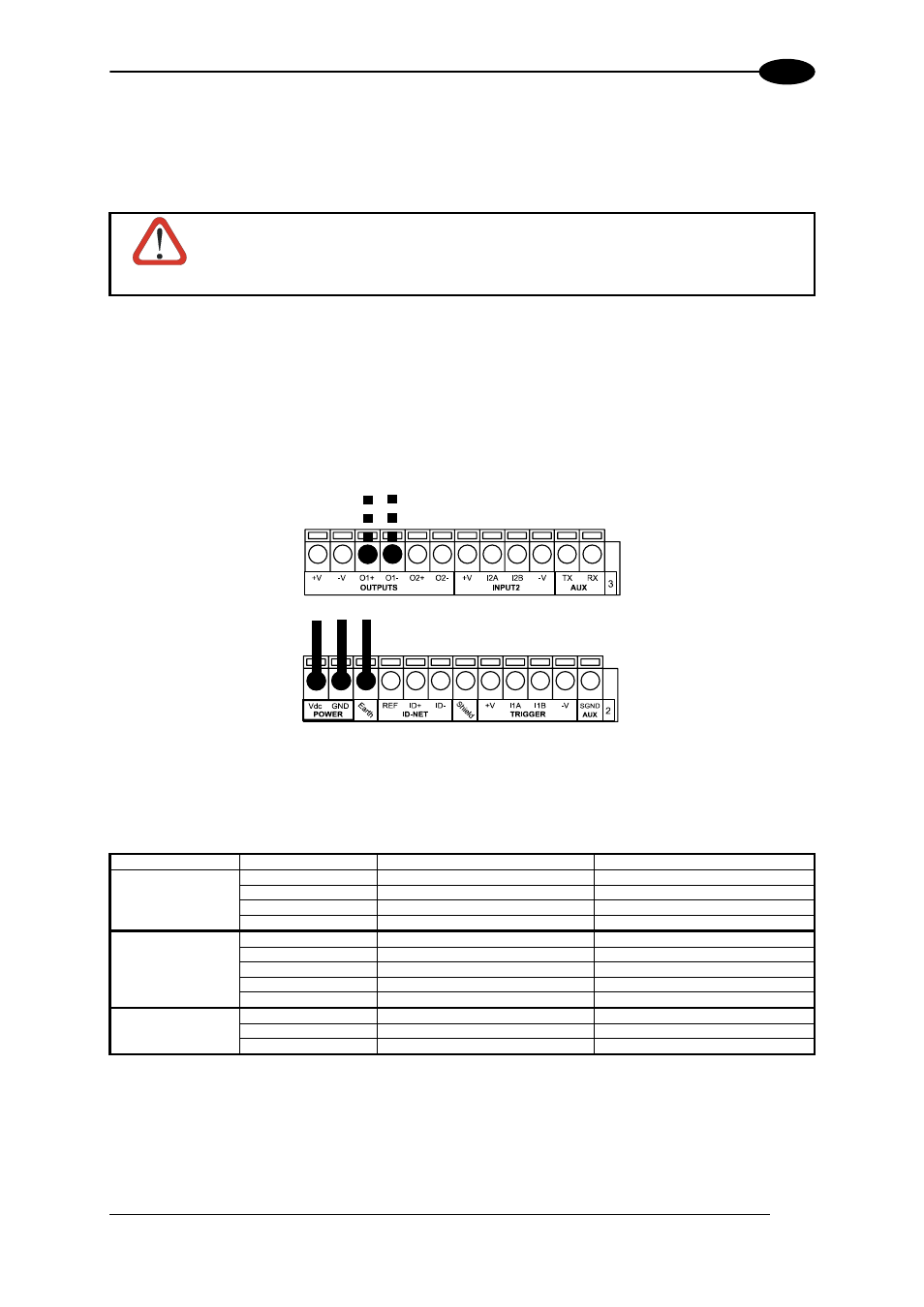
In the case of the LT-100, LT-200 or LT-300 illuminators, one of the available digital outputs
must be connected as the control signal. In VisiSet™, configure the Output Line Function
parameter to "External Lighting System" and the Matrix Output x External Lighting System
Mode parameter to "Triggered".
Control Signal for
LT-100, LT-200 or
LT-300 illuminators
Power to External
Illuminator
Figure 60 – External Lighting System Connections
Below is a table summarizing the various External Illuminator wiring and power requirements:
Illuminator
Wire Color
CBX/Matrix Signal
Meaning
LT-100
Red
Vdc
10 to 30 Vdc
LT-200 Black
GND
Ground
Blue
O1- or O2-
Control Signal -
White
O1+ or O2+
Control Signal +
LT-300
Brown
Vdc
10 to 30 Vdc
Black
GND
Ground
Yellow/Green
Earth
Shield/Earth
Ground
Blue
O1- or O2-
Control Signal -
White
O1+ or O2+
Control Signal +
LT-210, LT-314,
White
Vdc
24 Vdc
LT-316, LT-410
Black
GND
Ground
LT-510, LT-511
Shield
Earth
Shield/Earth Ground
41