Installation, Actual ta-24h type a terminal locations, Installation for wall mounting – Aiphone TA-12H User Manual
Page 2: Se parallel conductors, not twisted pairs
Attention! The text in this document has been recognized automatically. To view the original document, you can use the "Original mode".
F E A T U R E S
* A s m a n y as 12 simultaneous conversations are possible with a 24 station system.
* Conference calls can selectively include up to all stations in the system.
* Designed for either desk use or wall mounting.
»Any station can page through connected conventional paging or background music system using adaptor PG-U.
* Block paging and talkback paging is available when using adaptor PA-B.
* TA—12H and TA—24H phones can be intermixed to provide a communication system to meet your requirements.
INSTALLATION
Do not attempt to install your intercom system until you have read and thoroughly understood the installation
procedure. Aiphone’s warranty is void if system is installed in a manner other than described in this manual.
Lay out your system in advance. Determine the exact location of each station. We recommend a full comple
ment of wire be installed, even though you may not initially be installing the maximum number of stations available
to your system. This way, should you decide to add a station later, you can avoid running additional cables to
existing stations. Do not connect wires to terminal P3 unless appropriate equipment is used. Phone system will
not operate if this wire is connected in parallel through system.
W I R I N G
required
:
u
SE PARALLEL CONDUCTORS, NOT TWISTED PAIRS.
TA-12H - 18 Conductors maximum
TA-24H - 30 Conductors maximum
Refer to the chart below and select the proper wire gauge to meet your requirements.
AWG WIRE SIZE
24 AWG
22 AWG
20 AWG
18 AWG
DISTANCE
1300'
2300'
3300'
5000'
DIAMETER OF WIRE
0.5 mm
0.65 mm
0.8 mm
1.0 mm
DISTANCE
390 m
700 m
1000 m
1600 m
Begin your installation with station #1. A space is provided at the left of the diagram to write in your color
code. Note the position of the C terminal at each station. Be sure you wire each station correctly.
After installing your second station we recommend that the power supply be connected to the + and - terminal
lines at a convenient location and that a test be made for calling and talking between each station. As each addi
tional station is installed re-test between each station. Unplug power supply while making wiring connections.
To obtain the most efficiency from your power supply it is necessary to install the unit as near as possible
to the center of your communications network.
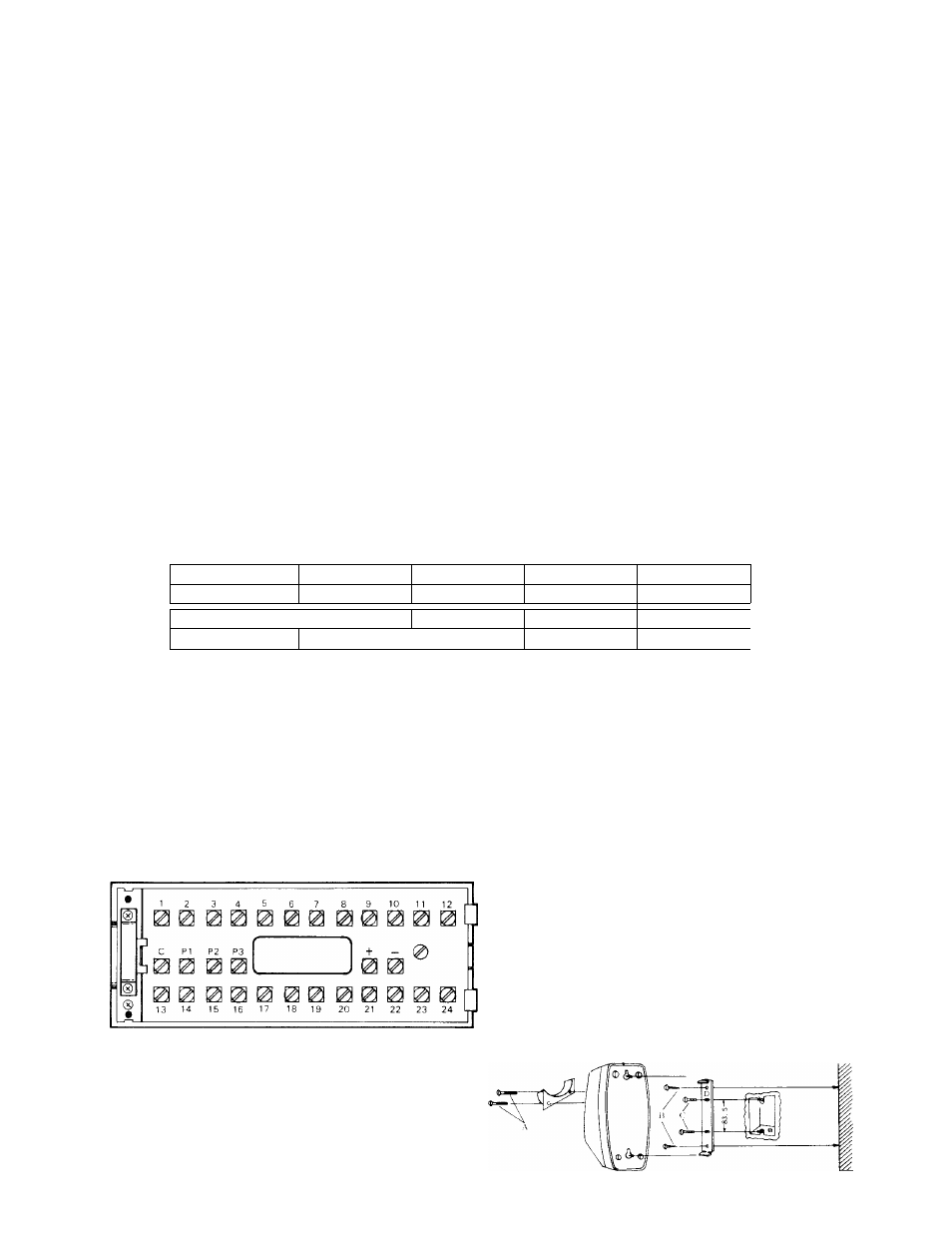
ACTUAL TA-24H TYPE A TERMINAL LOCATIONS
O- (^2^
: for connecting relative stations
: for power supply
: for receiving calls and talking
0 -
: for paging
fps) : for local speaker cutout
INSTALLATION FOR WALL MOUNTING
1) Attach the mounting bracket to wall or
single gang plaster ring.
2) Attach handset cradle included as shown in
illustration.