Installation – Aiphone VC-58MT User Manual
Page 4
Attention! The text in this document has been recognized automatically. To view the original document, you can use the "Original mode".
3
INSTALLATION
(1) ACTUAL TERMINAL LOCATION
© © © ©
1
2
3
4
B
.
VC-K INSIDE VIEW
+ - 1 2 3 4 B L+ L-
© © © © © © © © ©
VC-M PANEL BACK VIEW
m
m
m
m
m
ITTI
Q
: for communication (VC-K to entrance station)
: for communication (Entrance station to VC-K)
: for grounding
: for door release
: for call signal
: for power supply (DC 12V)
; for RY-PA or DC 12V door release.
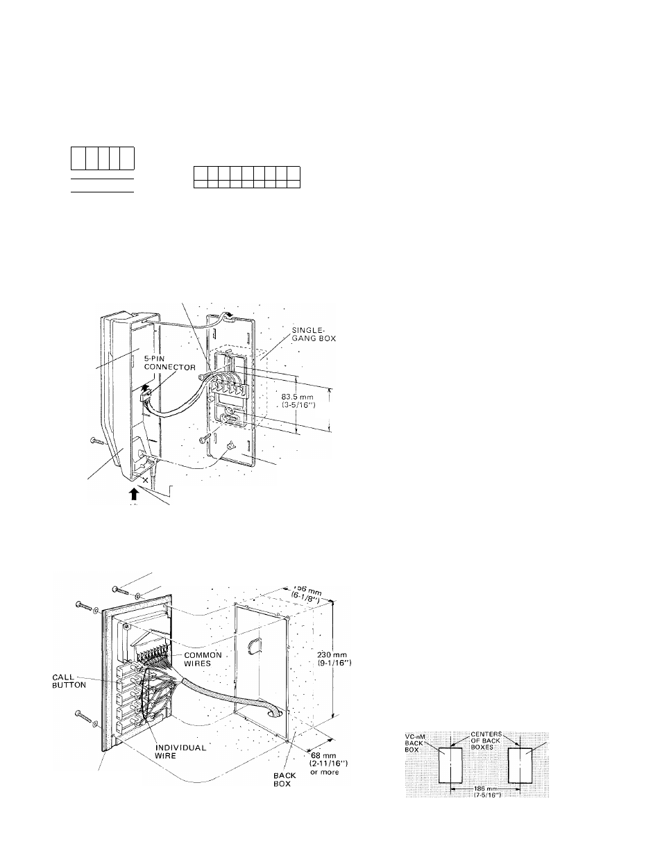
(2) WALL-MOUNTING INSTALLATION
VC-K
TERMINAL
SECTION
PC BOARD
60 mm
(2-3/8-)
VC-K
CHASSIS
When mounting VC-K to wall directly,
remove the bottom right part of front
case by nipper, etc. for cable inlet.
(1) Separate front case from chassis by removing
a screw and S-pin connector.
(2) Attach the chassis to either SINGLE-GANG
BOX or wall directly.
(3) Connect wires to terminals on chassis.
(4) Reattach the female connector to receptacle
on PC board.
Be careful with the sharp pins.
(5) Remount the front case.
VC-nM
-SCREW (x4)
WASHER (x 4)
(1) Cut out a hole in the wall of H; 230 mm (9-1/16")
X W: 156 mm (6-1/8"), securing depth of 68 mm
(2-11/16").
(2) Pass cable thru either of knock-out holes and
connect wires to terminals on back of front
panel.
(3) Attach the front panel to back box with the
supplied 4 screws.
NOTE; Be careful that the connected wires should be
put to either side neatly, in order not to
create shadows by the directory card illumina
tion.
When mounting VC-nM and VCH unit(s), put back
boxes in the wall with 186 mm (7-5/16") interval
between two box centers.
VC-nM
FRONT PANEL
-VCH H:
:
back
;
::
box
;