Wheel adjustment, 400 series lawn tractors, 300 series figure 17 – Bolens 300 Series User Manual
Page 14: Figure 18, Carburetor adjustment, Brake adjustment (see figure 19)
Attention! The text in this document has been recognized automatically. To view the original document, you can use the "Original mode".
Move the lock nut toward the tubing to s:art to
disengage the deck earlier. Move the lock nu: away
from the tubing to obtain more drive in the jutting
positions.
A
WARNING: Make certain the unit is ad
justed so that the cutting biadcs are
disengaged when the lift and diser gage-
ment lever is in the disengaged po »ition.
WHEEL ADJUSTMENT
The caster (forward slant of the king pin) a id the
camber (tilt of the wheels out at the top) require no ad
justment. Automotive steering principles have been
used to determine the caster and camber on the trac
tor. The front wheels should toe-in 1/8 inch.
To adjust the toe-in, follow these steps.
300 Series Lawn Tractors:
1. Remove the cotter pin and flat washer from
1
he fer
rule on the tie rod end on the right side of th e trac
tor. See figure 17.
2. Adjust the tie rod for correct toe-in by thread ng the
ferrule in or out as necessary. (See figuie 18.)
Reassemble the tie rod.
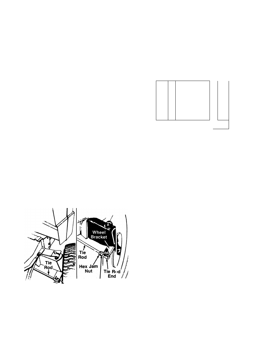
400 Series Lawn Tractors:
1. Remove the hex nut and lock washer, and drop
the tie rod end from the wheel bracket. See figure
13.
2. Loosen the hex jam nut on tie rod.
3. Adjust the tie rod assembly for correct toe-ir. (See
figure 18.) Retighten hex jam nut.
Ferrule
Cotter Pin and
Flat Washer
Hex Nut
Lock Washer
300 Series
FIGURE 17.
400 Series
Dimension “B” should be approximately 1/8" less than
Dimension “A.” See figure 18.
A. ) To increase Dimension “B,” thread the ferrule onto
the tie rod (300 Series) or thread the rod into tie
rod end (400 Series).
B. ) To decrease Dimension “B,” unscrew the ferrule
from the tie rod (300 Series) or unscrew the tie rod
from the tie rod end (400 Series).
C. ) Reassemble tie rod. Check dimensions. Readjust
if necessary.
r-
--------- A------------1
a
Front
L___
---------- B
(1/8" less than A)
FIGURE 18.
CARBURETOR ADJUSTMENT
A
WARNING: If any adjustments are made to
the engine whiie the engine is running
(e.g. carburetor), disengage ali clutches
and blades. Keep clear of all moving parts.
Be careful of heated surfaces and muffler.
Minor carburetor adjustment may be required to
compensate for differences in fuel, temperature,
altitude and load. To adjust the carburetor, refer to the
separate engine manual packed with your unit.
NOTE: A dirty air cleaner will cause an engine to run
rough. Be certain air cleaner is clean and attached to
the carburetor before adjusting carburetor.
BRAKE ADJUSTMENT
(See figure 19)
The brake is located by the left rear wheel inside the
frame. During normal operation of this machine, the
brake is subject to wear and will require periodic
examination and adjustment.
A
WARNING: Do not have the engine running
when you adjust the brake.
NOTE: Your brake may be equipped with a lock nut in
stead of the castle nut and cotter pin shown in figure 19.
To adjust the brake, remove the cotter pin from the
castle nut (if so equipped). Adjust the nut so the brake
starts to engage when the brake lever is V
a
" to 5/16"
away from the axle housing.
NOTE: Figure 19 is shown with the unit tipped up on
rear wheels for clarity only.
14