Operating the cutting blades, Adjustments, Seat adjustment – Bolens 300 Series User Manual
Page 12: Deck leveling adjustment, Speed cdntrdl adjustment (see figure 14)
Attention! The text in this document has been recognized automatically. To view the original document, you can use the "Original mode".
7. Place shift lever in either FORWAFiD or
REVERSE, and follow normal operating pro
cedures.
OPERATING THE CUTTING BLADES
The cutting blades may be engaged while the law n trac
tor is moving or standing still. DO NOT engage tl le cut
ting blades abruptly as the sudden belt tension on the
pulley may cause the engine to stall.
▲
WARNING: When the blade drive s en
gaged, keep feet and hands away frc m the
discharge opening, the blades or an / part
of the deck. When the unit is used for other
than mowing, the blade drive shoi id be
disengaged.
Move the lift and disengagement lever intD the
DISENGAGED position to raise the deck and
disengage the blades.
ADJUSTMENTS
SEAT ADJUSTMENT
To adjust the position of the seat, loosen the four self
tapping screws on the bottom of the seat. See figure
9. Slide the seat forward or backward as dosired.
Retighten the self-tapping screws.
DECK LEVELING ADJUSTMENT
If an uneven cut is obtained, the deck may be I jveled
as follows.
1. Move the lift and disengagement lever fi
(lower the cutting deck). Make certain th(
wheels (if so equipped) are not resting (
ground.
2. With unit on hard, level surface, measu
distance from the bottom edge of the centei
left side of deck to the ground. Measure the
distance just behind the chute area on th
side of the deck. Or, place the blades in a s
line, and measure the distance from the c
edge of the blade tips to the ground.
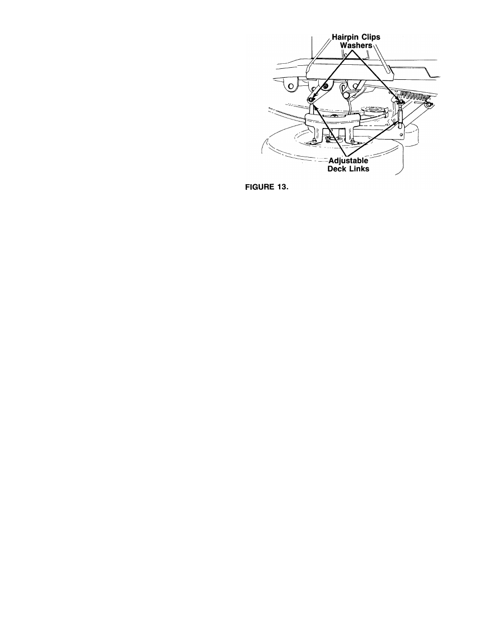
3. Disconnect the adjustable deck links from th
lift pivot brackets on the left side of the i
removing the hairpin clips and flat washer
figure 13.
4. Thread the adjustable links in or out as neci
Reassemble the links. Check the adjustmei
readjust as necessary.
>rward
) deck
)n the
re the
of the
same
3 right
freight
utside
3 deck
init by
3. See
ssary.
It,
and
2
.
3.
4.
SPEED CDNTRDL ADJUSTMENT (See Figure 14)
NOTE: When operating the unit initiaiiy or after replac
ing the belts, there will be little difference between the
highest two speeds until after the belts have gone
through a break-in period and have seated themselves
into the pulleys.
First, adjust the speed control lever as follows:
1. Place the shift lever in Neutral position.
Start the engine.
Place the speed control lever in high speed
position.
Release the clutch-brake pedal completely, then
slowly depress the pedal all the way (to disengaged
position). Hold the pedal in this position.
5. Turn the engine off.
6. After engine stops completely, release the clutch-
brake pedal.
7. Disconnect the speed control link from the variable
speed bracket by removing the hairpin clip and flat
washer from the stud located on the bottom side
of the variable speed bracket.
8. Depress the clutch-brake pedal forward until the
stop on the clutch-brake pedal assembly hits solid
ly against the underside of the frame.
9. Remove the hairpin clip and flat washer from the
rod attached to the back of the speed control lever.
Place the speed control lever in parking brake
position.
Thread the ferrule on the rod until the ferrule slips
into the bottom end of the slot in the speed con
trol lever, then thread the ferrule down on the rod
one full turn (to shorten).
Position speed control lever as follows:
a.
7-speed units: Place speed control lever in
second position.
10
.
11
12
12