Clutch-brake pedal, Parking brake, Ammeter (optional) – Bolens 300 Series User Manual
Page 10: Interlocks (not shown), Cutting controls, A. lift and disengagement lever, B. deck wheel height adjustment, Operation, Tire pressure, Gas and oil fill-up
Attention! The text in this document has been recognized automatically. To view the original document, you can use the "Original mode".
CLUTCH-BRAKE PEDAL
The clutch-brake pedal is located on the left side of the
lawn tractor. Depressing the clutch-brake pediil part
way disengages the clutch. Pressing the pedal all the
way down disengages the clutch and engages tf e disc
brake. See figure 11.
NOTE: The clutch-brake pedal must be depressed to
start the engine.
PARKING BRAKE
The speed control lever is used to set the parking Drake.
To set the parking brake, depress the clutch brake
pedal. Press the speed control lever inward and all the
way down. Release the speed control lever and the
clutch-brake pedal.
To release the parking brake, depress the clutch brake
pedal, press the speed control lever inward and move
to desired position. Release the speed control lev ?r and
the clutch-brake pedal.
NOTE: The parking brake must be set if the op drator
leaves the seat with the engine running.
AMMETER (Optional)
If your lawn tractor is equipped with an amme ter, it
registers the rate of battery charge or discharge). The
ammeter will register on the discharging side when
starting the engine. It should register on the op josite
side (charging) when the engine is running in the fast
position until the battery is completely charged With
a fully charged battery or with the engine idling, th
e
am
meter will not show a charge.
INTERLOCKS (Not Shown)
Interlock safety switches are located by the clutch brake
pedal, the lift and disengagement lever, the shift lever
and under the seat.
Before the engine will start, the clutch-brake pedal must
be depressed all the way and the lift and disengage
ment lever must be in the disengaged position.
Before the unit can be shifted into reverse or if the
operator leaves the seat, the lift and disengagement
lever must be in the disengaged position.
CUTTING CONTROLS
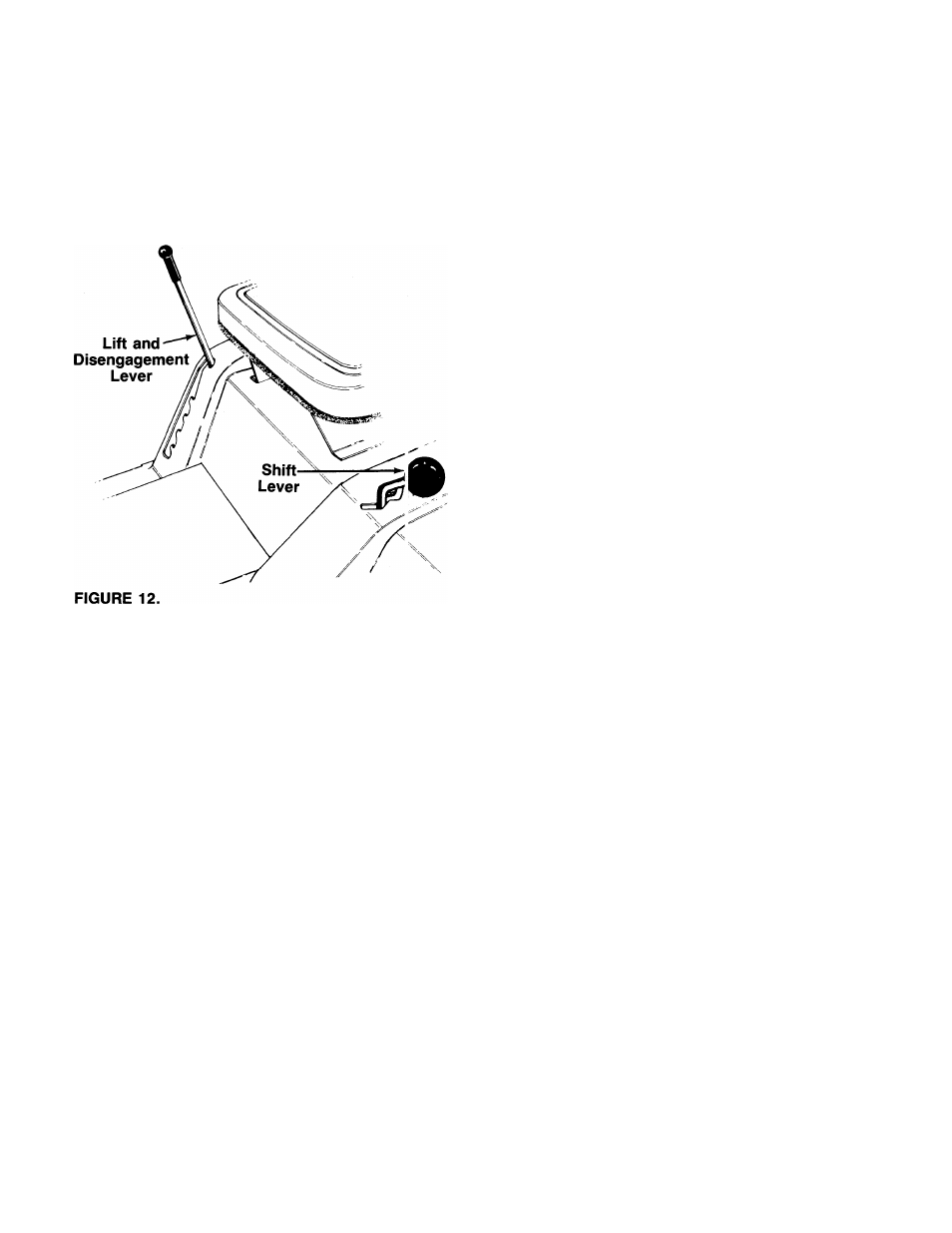
A. LIFT AND DISENGAGEMENT LEVER
The lift and disengagement lever is used to raise and
lower the cutting deck which determines the cutting
height. Pulling it all the way back and locking it
disengages the blades. The lift and disengagement
lever
must be in the disengaged position when start
ing the engine, when shifting into reverse or if the
operator leaves the seat. See figure 12.
B. DECK WHEEL HEIGHT ADJUSTMENT
Set the deck wheels (if so equipped) so that the wheels
are V
a
to V
2
inch above the ground, by moving the deck
wheels to the desired hole location in the deck.
OPERATION
A
WARNING
AVOID SERIOUS INJURY OR DEATH
GO UP AND DOWN SLOPES, NOT ACROSS. • AVOID SUDDEN TURNS.
DO NOT OPERATE THE UNIT WHERE IT COULD SLIP OR TIP.
IF MACHINE STOPS GOING UPHILL, STOP BLADE(S) AND BACK
DOWNHILL SLOWLY.
DO NOT MOW WHEN CHILDREN OR OTHERS ARE AROUND.
NEVER CARRY CHILDREN.
LOOK DOWN AND BEHIND BEFORE AND WHILE BACKING.
KEEP SAFETY DEVICES (GUARDS, SHIELDS, AND SWITCHES) IN
PLACE AND WORKING.
REMOVE OBJECTS THAT COULD BE THROWN BY THE BLADE(S).
KNOW LOCATION AND FUNCTION OF ALL CONTROLS.
BE SURE BLADE(S) AND ENGINE ARE STOPPED BEFORE PLACING
HANDS OR FEET NEAR BLADE(S).
BEFORE LEAVING OPERATOR’S POSITION, DISENGAGE BLADE(S),
PLACE THE SHIFT LEVER IN NEUTRAL, ENGAGE BRAKE LOCK, SHUT
ENGINE OFF AND REMOVE KEY.
READ OPERATOR’S MANUAL
TIRE PRESSURE
The tires on your unit may be over-inflated for shipping
purposes. Reduce the tire pressure before operating
the unit. Recommended operating tire pressure is ap
proximately 12 p.s.i. (check sidewall of tire for tire
manufacturer’s recommended pressure).
A
WARNING: Maximum tire pressure under
any circumstances is 30 p.s.i. Equal tire
pressure should be maintained on all tires.
GAS AND OIL FILL-UP
NOTE: To open the hood, simply lift up on both sides
of the hood.
10