Neutral adjustment (wheel drive), Cutting deck engagement adjustment – Bolens 300 Series User Manual
Page 13
Attention! The text in this document has been recognized automatically. To view the original document, you can use the "Original mode".
'N.
b.
5-speed units: Place speed control lever in first
position.
13. Place ferrule into speed control lever slot, and
secure with flat washer and hairpin clip. Release
the clutch-brake pedal.
Speed
.Control Hairpin Clip
n
Lever and Flat Washer
‘ '
:/
Neutral
Slot
-, V' '
Slot Clutch-Brake
Pedal
Ferrule
Variable
Speed Speed
Bracket Control
Link
Hairpin Clip
and Flat Washer
FIGURE 14.
Next, adjust the speed control link as follows to obtain
the correct neutral adjustment.
1. Push the clutch-brake pedal backward by hand as
far as it will go using light pressure. Hold it in this
position as you make the following adjustment.
2. Thread the speed control link into or out of the fer
rule until the eyelet on the opposite end of the link
slips onto the stud on the bottom side of the
variable speed bracket.
3. Secure the speed control link to the variable speed
bracket with flat washer and hairpin clip.
NEUTRAL ADJUSTMENT (Wheel Drive)
1. Place the transmission in neutral. (The unit will
move freely when pushed forward and backward
with the parking brake released.)
2. Loosen the bolt which secures the shift lever
assembly to the shift lever adjusting link. See figure
15.
3. Place the shift lever in the netural slot. See figure
15.
4. Tighten the bolt to 13 foot pounds.
Shift
Lever
Loosen
Hex Bolt
FIGURE 15.
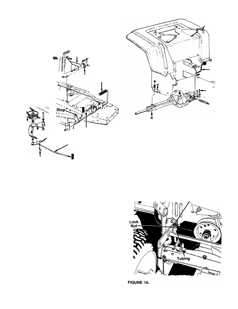
CUTTING DECK ENGAGEMENT ADJUSTMENT
The cutting deck engagement may be adjusted to make
certain deck is disengaged when lift and disengage
ment lever is in the disengaged position, or to obtain
more drive in the cutting positions. Correct adjustment
as follows.
Place the lift and disengagement lever in the highest
cutting position (first notch down from disengaged posi
tion). The approximate adjustment is to have the lock
nut on the threaded rod (above the rear of the deck)
touching the end of the tubing. See figure 16.
Threaded
Rod
13