Blade mounting torque, Fuel filter, Drive belt removal and replacement – Bolens 135-688-000 User Manual
Page 17: Note, Rear drive belt, Front drive belt
Attention! The text in this document has been recognized automatically. To view the original document, you can use the "Original mode".
Blade Mounting Torque
3/8" Dia. Bolt 375 in. lb. min., 450 in. lb. max.
5/16" Dia. Bolt 150 in. lb. min., 250 in. lb. max.
To insure safe operation of your unit, ALL nuts
and bolts must be checked periodically for correct
tightness.
FUEL FILTER
Your unit is equipped with a replaceable in-line
fuel filter. Replace filter whenever contamination
or discoloration is noticed. Order replacement
filter through your engine authorized service
dealer.
Transmission
Shift Lever Bracket
DRiVE BELT REMOVAL AND REPLACEMENT
A C
WARNiNG
Disconnect the spark plug wire and
ground it against the engine. Block
the wheels of the unit.
NOTE
Figures 25 through 28 are shown
with the unit tipped up for clarity.
It is not necessary to tip the unit
to remove the belts.
Rear Drive Belt
1. Remove the two truss head screws which
secure the transmission cover. See figure 5.
2. Lift the transmission cover. Unplug the green
safety wire from beneath the transmission
cover. Refer to figure 6. Remove transmission
cover.
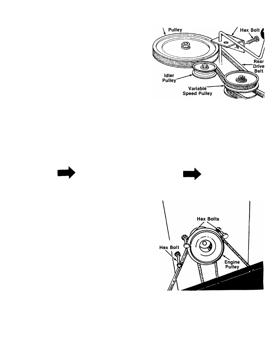
3. Push the idler pulley toward the right side of
the unit. Lift the belt over the idler pulley. See
figure 24.
4. Remove the belt from the variable speed
pulley.
5. Remove the two bolts which hold the shift
lever bracket to the frame on the left side of
the unit. Swing the bracket toward the right so
the belt can be removed from the transmis
sion pulley. See figure 24.
6. Replace belt, and reassemble in reverse order.
FIGURE 24.
Front Drive Belt
1. To remove the front drive belt, first remove the
rear drive belt from the idler pulley and
variable speed pulley.
2. Place the lift lever in the disengaged position.
3. Remove the three hex bolts (belt keepers)
from the engine pulley belt guard. See figure
25.
NOTE
Make certain hex bolts are reassem
bled as shown in figure 25.
FIGURE 25.
4. Unhook the deck belt from the engine pulley.
5. Remove the two bolts, lock washers and nuts
on each side of the frame which hold the
engine pulley belt guard to the frame. See
figure 26.
17