Note, Parking brake, Lift and – Bolens 135-688-000 User Manual
Page 11: Incline assistance brake, Cutting controls, A. lift and disengagement lever, B. deck lift indicator, C. wheel height adjuster, Setting the cutting height
Attention! The text in this document has been recognized automatically. To view the original document, you can use the "Original mode".
NOTE
The clutch-brake pedal must
depressed to start the engine.
be
PARKING BRAKE
The speed control lever is used to set the parking
brake. To set the parking brake, depress the
clutch-brake pedal. Press the speed control lever
outward and all the way to the rear of the unit.
Release the speed control lever and the clutch-
brake pedal.
To release the parking brake, depress the clutch-
brake pedal, press the speed control lever outward
and move to desired position. Release the speed
control lever and the clutch-brake pedal.
Lift and
Disengagement
Lever
Speed
Control
‘Lever
Deck.
Lift
Indicator
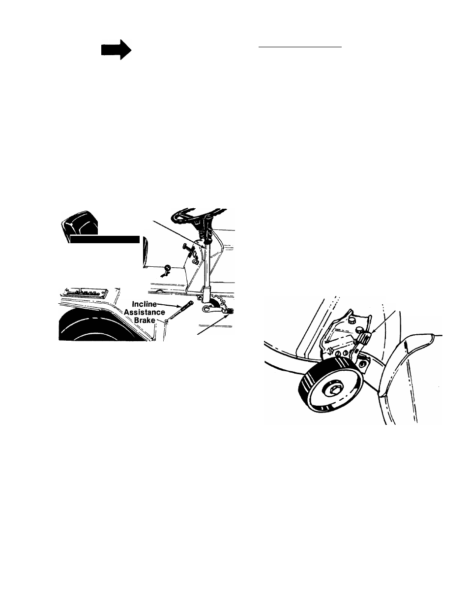
FIGURE 17.
INCLINE ASSISTANCE BRAKE
When stopping on a hill, hold the incline
assistance brake lever back while you release the
clutch-brake pedal until the lawn tractor begins to
move, then release the lever. This lever permits
smoother starts and clutch engagement by
holding the tractor during the brake release/clutch
engagement operation. See figure 17.
INTERLOCKS (Not Shown)
Interlock safety switches are located on the
clutch-brake pedal, and the lift and disengage
ment lever and gear shift lever.
Before the engine will start, the clutch-brake
pedal must be depressed all the way and the lift
and disengagement lever must be in the disen
gaged position.
Before the unit can be shifted into reverse, the lift
and disengagement must be in the disengaged
position.
CUTTING CONTROLS
A. LIFT AND DISENGAGEMENT LEVER
The lift and disengagement lever is used to raise
and lower the cutting deck. Pulling it all the way
back and locking it disengages the blades. The lift
and disengagement lever must be in the disen
gaged position when starting the engine and
when shifting into reverse. See figure 17.
B. DECK LIFT INDICATOR
The deck lift indicator marks the position being
used for the lift lever. Select the lift lever position
desired, press the indicator lever outward, move it
to the position immediately below the lift lever
and release the indicator lever. See figure 17.
C. WHEEL HEIGHT ADJUSTER
Move the lever towards the wheel and set it in the
desired height. See figure 18.
Wheel Height
Adjuster
FIGURE 18.
3. SETTING THE CUTTING HEIGHT
1. Select the position for the lift lever which
gives the desired cutting height. Move the
deck lift indicator so that the lift lever can be
returned to the same position after it is raised.
2. Set the wheel height adjusters on the deck so
that the wheels are V4 to Vz inch above the
ground.
11