Sequence of operation—heating, Sequence of operation—cooling, Ímüwu – Bryant 394B User Manual
Page 6
Attention! The text in this document has been recognized automatically. To view the original document, you can use the "Original mode".
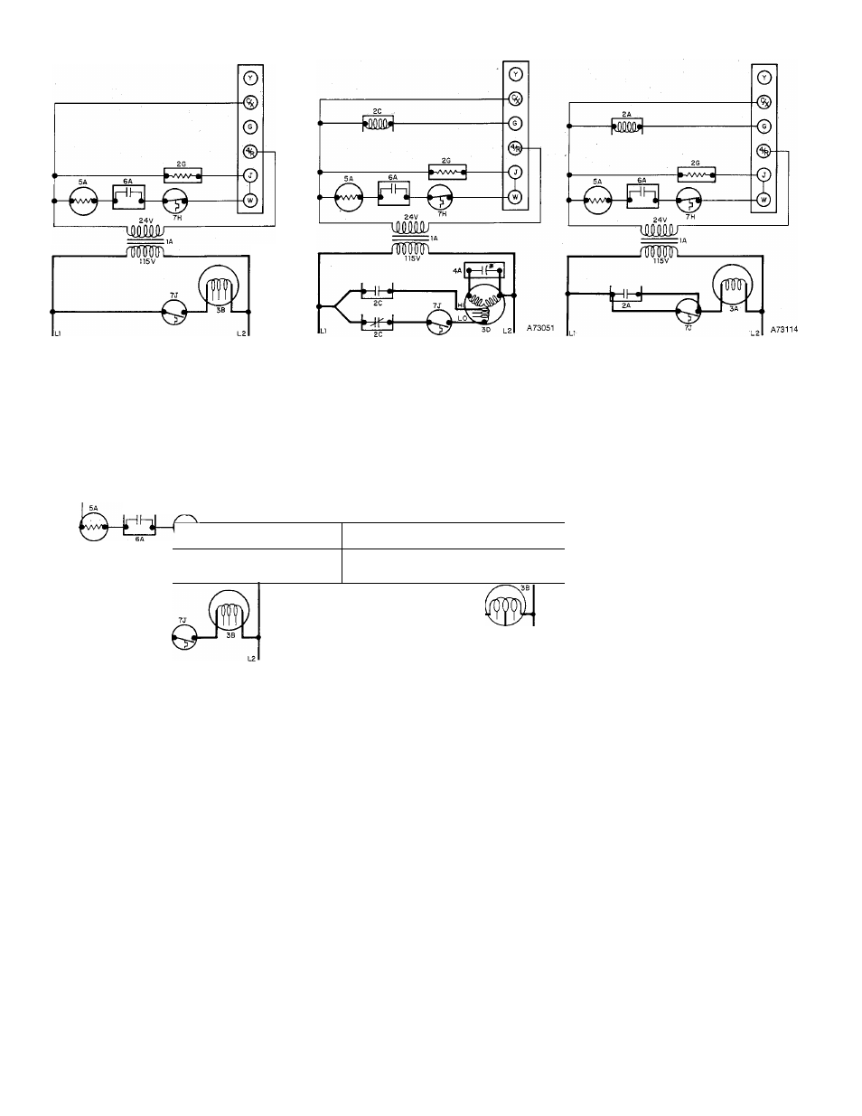
LINE-TO-LINE WIRING DIAGRAMS
Figure 9 - Units with 1/10-, 1/6-, or 1/5-KP Direct-
Drive Motor (no cooling fan relay)
Figure 10 - Units with 1/6-, 1/3-, 1/2-, or 3/4-HP
Direct-Drive Motor (cooling fan relay).
No Capacitor on 1/6- and 1/3-HP
Motors.
—Mna4----------------------
JE.
JiL
Figure 11 - Units with 3/4-HP Belt-Drive Motor
(cooling fan relay)
LEGEND
1 A-Transformer
2A-Cooling Fan Relay
2C-Cooling Fan Relay
2G-Fleatlng Fan Relay
3A-Fan Motor SP PH
3B-Fan Motor SP
3D-Fan Motor PSC
j
WM
H 5 V
R
2 4 V
___ a
4A-Capacitor (None on 1/6-
& 1/3-HP Motors)
l A
____
________________________
íMüWu
_________
5A-Gas Valve
6A-Pllot (None on LP)
/
A73053
■fciti-
fepi—©■
7J-Fan Control SPST N.O.
If any of the original wire, as supplied, must be
replaced, use same type or equivalent wire.
Figure 12 - 50,000-Btuh Unit with B or D controls
(no cooling fan relay)
Figure 13 - 50,000-Btuh Unit with B or D Controls
(cooling fan relay)
SEQUENCE OF OPERATION—HEATING
The pilot (6A) must be lit, closing its contacts, before
the gas valve (5A) will open. If, for some reason, the
gas valve does not open when thermostat calls for
heat, heat assist coil (2G) causes heating relay (7J) to
close its contacts, energizing blower motor (3A, 3B, or
3D).
When the thermostat calls for heat, the control circuit
is closed between terminals (4 and W). Power from
transformer (lA) energizes automatic gas valve coil
(5A) and heat assist coil (2G) simultaneously. After a
short time delay, automatic gas valve (5A) opens, per
mitting gas to flow to the burners where it is ignited
by the gas pilot. After another delay, the heating relay
switches its contacts (7J), energizing blower motor
(3A, 3B, or 3D) on heating speed.
When the thermostat is satisfied, the circuit between
terminals (4 and W) is broken, deenergizing
automatic gas valve coil (5A) and heat assist coil
(2G). After a few seconds, automatic gas valve (5A)
closes, stopping’the flow of gas to the burners. After a
longer delay, heating relay (7J) opens its contacts to
stop blower motor (3A, 3B, or 3D).
If the furnace overheats for any reason, limit control
(7H) will switch, breaking the circuit to automatic gas
valve coil (5A). After a short delay, the gas valve
closes, shutting off the flow of gas to the burners.
The furnace will continue to cycle until the fault is
corrected.
SEQUENCE OF OPERATION—COOLING
When the thermostat calls for cooling, power from
transformer (lA) energizes cooling relay coil (2C),
closing its contacts, and energizing blower motor (3A,
3B, or 3D) on its cooling speed. It continues to operate
until the thermostat is satisfied.
When the thermostat is satisfied, the circuit to ter
minal (G) is broken, deenergizing cooling relay coil
(2C) which, in turn, opens its contacts, stopping
blower motor (3A, 3B, or 3D).
—6—