Thermostat location, Electrical connections low-voltage wiring – Bryant 394B User Manual
Page 3
Attention! The text in this document has been recognized automatically. To view the original document, you can use the "Original mode".
TO HEATING AND
COOLING CONNECTIONS
OF THERMOSTAT
_A
TO CONDENSER
CONTACTOR COIL
CONNECTIONS
TO HEATING AND
COOLING CONNECTIONS
OF THERMOSTAT
TO CONDENSER
LOW-VOLTAGE LEAD
OR TERMINAL STRIP
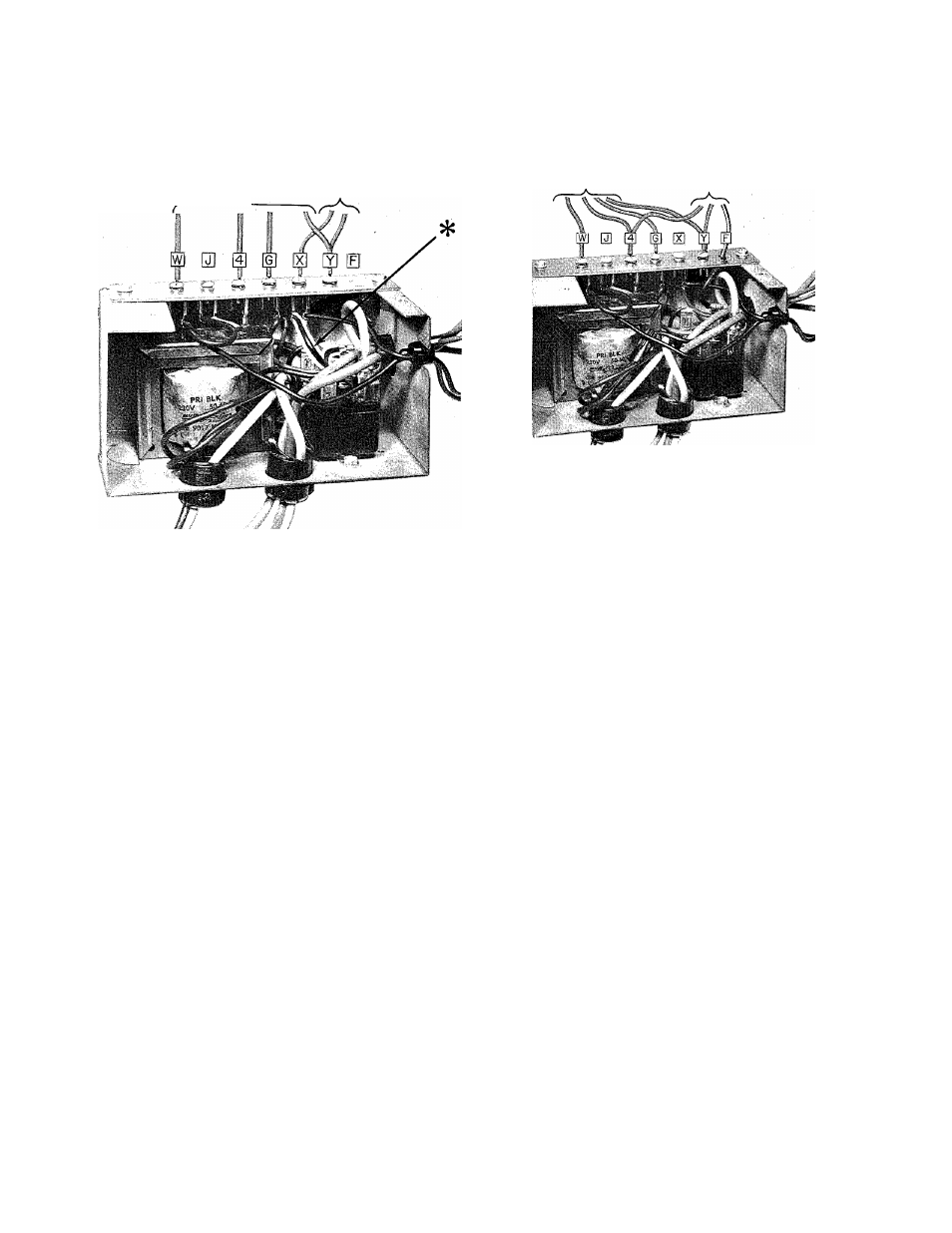
NOTE:
WIRE WITH * IN FIGURE 3 IS
REMOVED AND DISCARDED WHEN
CONDENSER HAS TRANSFORMER.
A73118
Figure 3—Control Box, Cover Removed,
No Internal Wiring Changes
Figure 4—Control Box, Cover Removed,
Showing Internal Wiring Changes
The 175,000-Btuh belt-drive, and 200,000-Btuh units
are equipped with a Honeywell fan limit control. It
provides control of fan operation and high-limit tem
perature protection. The fan switch makes contact to
start the blower motor on temperature rise to set
point. The limit switch breaks the circuit to the burn
ers when the temperature rise reaches the set point.
Thermostat Location
The room thermostat should be located where it will
be in the natural circulating path of room air. Avoid
locations where the thermostat would be exposed to
cold air infiltration, drafts from windows, doors, or
other openings leading to the outside, or exposure to
air currents from warm or cold air registers; or to ex
posure where the natural circulation of the air is cut
off—such as behind doors, above or below mantels,
shelves, etc.
The thermostat should not be exposed to heat from
nearby fireplaces, radios, televisions, lamps, or rays
from the sun. Nor should the thermostat be mounted
on a wall containing pipes or warm air ducts, or a flue
or vent that could affect its operation and prevent it
from properly controlling the room temperature. Any
hole in the plaster or panel through which the wires
pass from the thermostat should be adequately sealed
with suitable material to prevent drafts from affecting
the thermostat.
Set the thermostat heat anticipator at 0.5.
If additional controls are connected in the thermostat
circuit, the amp draw must be added to these settings.
Failure to make the settings will result in improper
operation of the thermostat.
ELECTRICAL CONNECTIONS
Low-Voltage Wiring
Field low-voltage connections are made at the low-
voltage terminal strip. See Figure 3. For Model 394
Furnaces used in conjunction with electric or gas air
conditioning units that do not have an integral trans
former, see Figure 3. If the 394 Furnace is used in con
junction with an electric or gas air conditioning unit
having an integral transformer, see Figure 4.
Figure 4 shows a field-installed wire running from
one side of the air conditioning transformer, through
the hole marked “F” in the terminal strip, to the
blower relay in the control box for the Model 394 Fur
nace. The wire marked * in Figure 3 is removed from
the control box and discarded.
NOTE: For heating-only connections, See Figure 8. For
heating and cooling connections, see Installation In
structions packaged with condensing unit.
—3—