Line-voltage wiring, Startup and adjustment, Adjustment of blower speed – Bryant 394B User Manual
Page 4: Table iii, Speed selector
Attention! The text in this document has been recognized automatically. To view the original document, you can use the "Original mode".
Line-Voltage Wiring
All electrical connections are to made in accor
dance with the local electrical codes. The unit must be
grounded electrically in accordance with National
Electric Code and local codes governing such in
stallations. A permanent and uninterrupted or un
broken ground is essential to minimizing personal in
jury if an electrical fault should occur. A permanent,
separately fused electric power supply, complete with
manual switch, should be provided for the furnace.
Field wiring connections should be made in accor
dance with the unit wiring diagrams.
When making aluminum conductor connections to
copper conductors or terminals, use only connectors
that are UL approved (marked Al/Cu with the UL
symbol) for the application and wire size. Do not
reduce wire size to fit connector by cutting off strands.
Use proper size connector.
After insulation has been stripped from the aluminum
conductor, coat the conductor end with corrosion
inhibitor (Burndy “Penetrox A” or equivalent), and
wire-brush the aluminum surface thru the inhibitor.
CAUTION: Do nor wire-brii.sh connectors atul lug.s.
The plating will be broken.
After cleaning, recoat the aluminum conductor with
inhibitor, and make connection, then coat entire con
nection. If applicable, wrap the connection for
moisture and/or electrical protection.
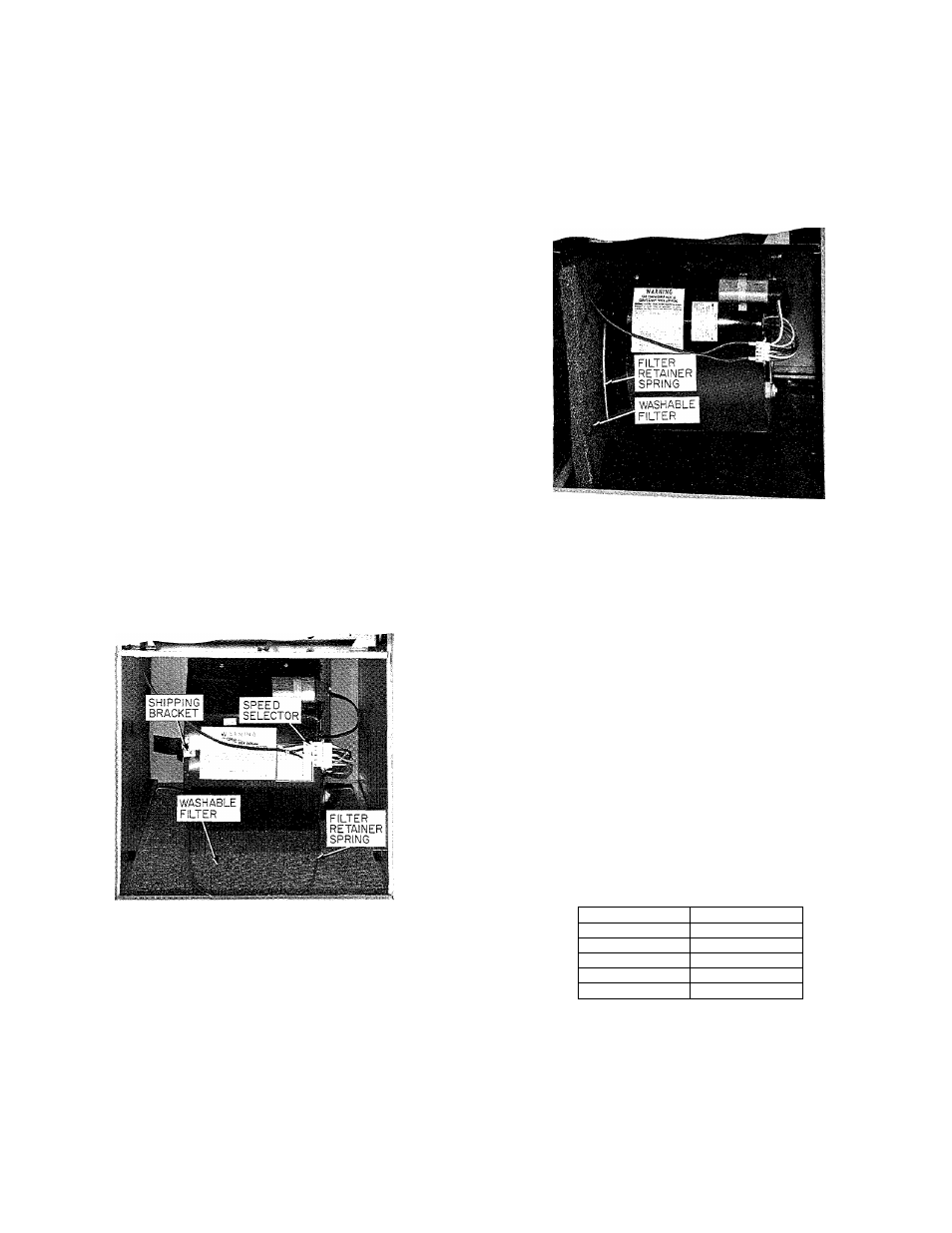
A73115
Figure 5—Filter Installed For Bottom Inlet
Filters
The filters are factory-installed in the bottom of the
furnace. This is for bottom inlet application. See
Figure 5.
For side inlet application, see Figure 2 and Table I
for the opening size. Remove the filter and the
retainer spring from the bottom opening. Install the
retainer spring in the holes provided, one in the
blower deck and the other in the retainer spring
bracket. See Figure 6.
CAUTION: Re sure ihe filiej- relainiM- spring is
behind rile flange of the casing side.
When the side inlet is used, the bottom opening
should be properly and permanently sealed.
NOTE: Side inlet application of sizes 048100, 060125,
060150, 060175, and 060200 requires use of the ap
propriate optional external filter rack. See in
structions packed with filter rack for installation.
Figure 6—Filter installed For Side Inlet
NOTE: Some units with direct-drive blowers have a
shipping bracket. See Figure 5. This bracket should be
removed and discarded. Belt-drive units have wood
shipping blocks that are to be removed and discarded.
STARTUP AND ADJUSTMENT
In addition to the following information, refer to
“Procedures for Gas Furnace Installation” packaged
with the unit.
Adjustment of Blower Speed
Four-Speed Direct Drive
To change motor speed taps, remove the motor tap
lead (see Figure 5) and relocate it on the desired ter
minal on the plug-in terminal block/speed selector
located on the blower.
TABLE III
SPEED SELECTOR
Speed
Tap No.
Common
C
Hi
1
Med-Hi
2
Med-Lo
3
Lo
4
Belt Drive
The blower speed may be changed by opening or
closing the motor pulley. When adjusting blower
speed, be certain that the pulleys are properly aligned.
CAUTION: When adjusting the blower speed, make
certain that the temperature rise across the bear ex
changer does not exceed that specified on ilie rating
plate.