Steering adjustment, Units with adjusteble tie rod) – Bolens TRANSMATIC LAWN TRACTOR 660 User Manual
Page 19
Attention! The text in this document has been recognized automatically. To view the original document, you can use the "Original mode".
* Remove the shift cover pane! and locate the speed
controi rod. See Figure 18.
NOTE: There is a small yellow wire connected to a
spring switch on the underside of the shift cover panel.
Be careful not to damage it when removing the panel.
*
Remove the hairpin dip which secures the speed
control rod’s ferrule to the speed bracket. See
Figure 18.
At the factory, the speed control rod is adjusted so that
5/8~in. of the rod is exposed beyond the ferrule.
*
Adjust the speed control by threading the ferrule
inward so that
no more than 3/4-in. of the rod
is
exposed beyond the ferrule.
See Figure
19.
*
* Reassemble the shift cover panel, start the tractor’s
engine and test the full range of speeds.
IMPORTANT:
If the above adjustment did not result in
the tractor obtaining the full range of speeds, see an
authorized service dealer to have the variable speed
drive system inspected and professionally adjusted.
Steering Adjustment
(Units With Adjusteble Tie Rod)
if the tractor turns tighter in one direction than the other,
or if either the tie rod and ferrule are being replaced due
to damage or wear, the tie rod may need to be adjusted.
To do so, proceed as follows:
NOTE: A replacement cotter pin (part no. 714-0470)
is needed to complete this adjustment. Have one on
hand before proceeding.
*
Place the steering wheel in position for straight
ahead travel.
*
In front of the pivot bar, measure the distance
horizontally from the inside of the left rim to the
inside of the right rim. Note the distance.
*
Behind the pivot bar, measure the distance
horizontally from the inside of the left rim to the
inside of the right rim. Note the distance.
*
The measurement taken in front of the pivot bar
should be between 1/16' and 5/16" less than the
measurement taken behind the pivot bar. if it is not,
an adjustment is necessary. Proceed as follows.
*
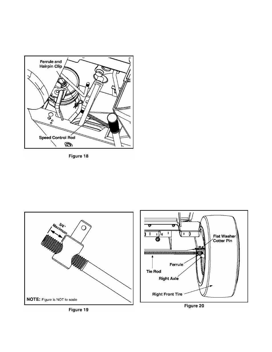
Locate the ferrule at the right end of the tie rod, just
to the rear of the right, front tire of tractor. See
gure 20.
* Reinsert the fer ru le and re-secu re the rod with the
cotter pin removed earlier.
Remove the cotter pin and flat washer which
secures the adjustment ferrule to the tractors right
axle.
19