Aaiphone – Aiphone AN-8050DS User Manual
Page 2
Attention! The text in this document has been recognized automatically. To view the original document, you can use the "Original mode".
4.3. Type of Cable
The types of cables are to be determined according to the
following conditions.
Twisted pair wires (such as those used for electronic
push-button telephone) are to be used for wiring between
the Exchange and the stations in principle.
The number of cables pairs laid should be determined
considering the possibility of future expansion of the
system.
Outdoor wires should be used where wiring passes
through Inaccessible areas such as ceilings or under floors
where the maintenance is not performed. Indoor wires
may also be used, however, in case where there is no risk
of deterioration due to exposure to heat, etc.
Note
Specifications related to each junction are as follows.
Mini-clamp connector (AN-8000EX line terminal)
Conductor diameter:
0O.4 - 0.65 mm (AWG22 ■
solid wire
Outside diameter:
01.05 mm or below
26),
Clip terminal (E-7000TB)
Conductor diameter:
0O.4 - 0.8 mm (AWG20 - 26),
solid wire
Outside diameter:
01.5 mm or below
Terminal station (LINE, H, C terminals)
Conductor diameter:
0O.4 - 1.3 mm (AWG16 - 26),
solid wire, stranded wire
4.4. Relations Between Core Diameter of Cable
and Maximum Cable Length
Referring to the following chart as guidelines, design the
distance between the Exchange and stations so that loop
resistance becomes 170 Q or less.
Conductor
diameter
(mm)
Loop
resistance
(Q/ km)
Maximum cable length
between the Exchange and station.
(Assuming that the loop resistance is 170 i).)
0O.4
295
570 m
0O.5
187
900 m
00.65
113
1.5 km
0O.9
58
2.9 km
4.5. Terminal Station Connection
Step 2.
Step 3.
Loosen the terminal screws and insert the cables.
Tighten the terminal screws securely.
Notes
•Tug lightly on the cable to be sure that it does not
pull free. If the cable pulls free, loosen the
terminal screw again and reconnect from Step 2.
•To
avoid
stripping
the
screws, use the
screwdriver appropriate to the screws tightened
into the terminal plug.
Tighten
Terminal screw
Cable
4.6. Mlnl-clamp Connector Connection
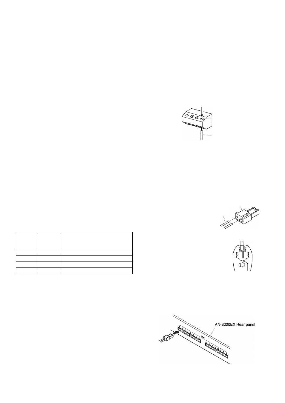
Connect the mini-clamp connector supplied with the AN-
8000EX to a cable using a commercially available tool
(pliers).
Step 1.
Cut off two-cable ends in equal length, and insert
them securely to a cover section (transparent side)
of the mini-clamp connector.
Note
pover
Insert the cable without ^transparent siae)
stripping the cable jacket.
Cable
Step 2.
With a pair of pliers, lightly ,
pinch the mini-clamp cover
and, after ensuring that the
cable Is securely inserted,
firmly squeeze on the cover.
Note
Squeeze on the mini-clamp cover until It is
correctly locked.
Step
1. Strip a cable jacket of approx 7 mm to expose
inner cable.
For cables, refer to The Type of Cables.
Step
3. Insert the wired connector (plug) into the
exchange's connector (socket) until it locks into
place.
7 mm
Note
Do not solder plate on exposed inner cables when
using a stranded wire.
AAIPHONE'