Figure 10, To stop engine, To engage drive – Bolens 120-270A User Manual
Page 8: Important, Adjustments, Caution, Cutting height, Note
Attention! The text in this document has been recognized automatically. To view the original document, you can use the "Original mode".
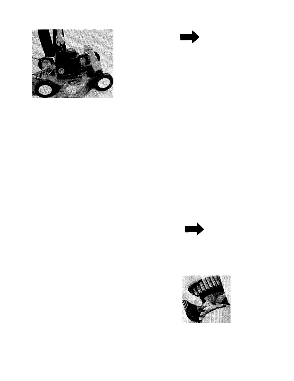
FIGURE 10.
4. After engine starts, move throttle control lever
to desired speed.
TO STOP ENGINE
1. Move throttle control lever to “STOP” posi
tion.
2. Remove spark plug wire from spark plug and
ground to prevent accidental starting while
equipment is unattended.
TO ENGAGE DRIVE
Move the handle forward for self-propelled opera
tion. The drive pinions will engage with the gear
tread tires, and forward drive results.
To stop the forward drive, release the handle. The
unit will be free-wheeling. Self-propelled drive is
resumed when handle is raised.
When operating this mower, unnecessary or ex
cessive engaging of the drive pinions with the
wheels should be avoided. Minimize the number
of times the handle is raised and lowered. Failure
to observe this operating rule can reduce the ser
vice lift of the front tires and drive pinions
substantially. When engaging the self-propelled
mechanism, a slight forward push on the mower
as the drive pinions and the gear tread tires mesh
will add to smoother and quieter operation and
will add substantially to the service iife of both the
tires and the drive pinions.
Be sure that lawn is clear of stones, sticks, wire,
or other objects which could damage lawn mower
or engine. For best results and to insure more
even grass distribution, do not mow when lawn is
excessively wet.
IMPORTANT
After striking a foreign object, stop
the engine. Remove wire from spark
plug, thoroughly inspect the mower
for any damage, and repair the
damage
before
restarting
and
operating the mower.
ADJUSTMENTS
A
CAUTION
Do not at any time make any adjust
ment to lawn mower without first
stopping engine and disconnecting
spark plug wire.
CUTTING HEIGHT
An adjusting plate and thumb lever at each wheel
position provides cutting height adjustment. Each
adjusting plate has five holes. Height of cut will
be changed when the thumb lever is moved from
one hole to another. Simply depress the lever
towards wheel and move wheel and lever
assembly to desired position. See figure 11.
Cutting height will be raised as the levers are
lowered. Cutting height wili be lowered as the
levers are raised. Ali wheels must be positioned at
the same height.
For rough or uneven lawns, move the wheels to a
position which will give a higher cutting height.
NOTE
Clutch rod must be adjusted each
time cutting height is changed.
I
Nil
FIGURE11.