Assembly, Instructions, Figure 1 – Bolens 120-270A User Manual
Page 4: Figure 2, Inner hole, Assembly instructions
Attention! The text in this document has been recognized automatically. To view the original document, you can use the "Original mode".
A
B-
E-
F-
'
N N
'w
ASSEMBLY
INSTRUCTIONS
Contents of Hardware Pack
A (3) Hairpin Cotters
B (1) Ferrule
C (2) Curved Carriage Boits 5/16-18
X
1.75" Long
-D (2) Hand Knobs
E (1) Hex Bolt 1/4-20x 1.50" Long
F (1) Hex Center Lock Nut 1/4-20 Thd.
G (2) Cable Ties
FIGURE 1.
Hairpin
Cotter (A)
Handle
Mount
Bracket
FIGURE 2.
\ Inner
Hole
(For Operation)
1.
2
.
3.
Remove the lawn mower, loose parts, hard
ware pack and literature from the carton.
Make certain all parts and literature have been
removed before the carton is discarded.
Extend the throttle control which is attached
to the engine at the rear of the mower and
place on the floor. Be careful not to bend or
kink control wire.
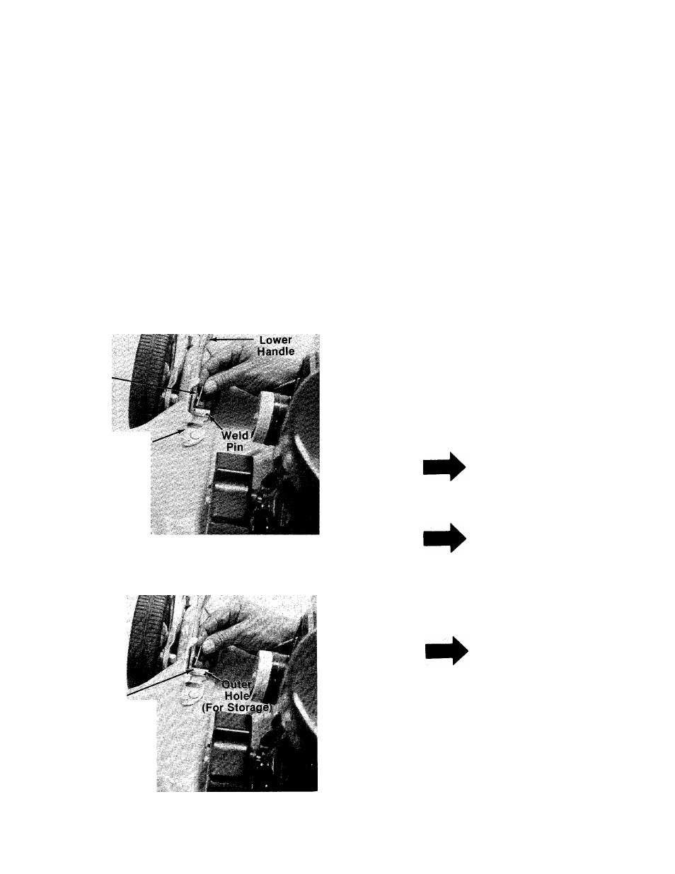
Fasten lower handle in position over weld
pins in handle mount brackets on deck. The
hole in the lower handle must be on the left
side of the unit. Secure with hairpin cotters in
inner hole on weld pin. See figure 2.
NOTE
Reference to right hand or left hand
side of the mower is observed from
the operating position.
NOTE
It may be necessary to pull open the
ends of the lower handle. This will
insure a tight fit when assembled in
to handle mount brackets.
NOTE
There are two (2) holes in the handle
mount brackets. Place the lower
handle against the brackets and
secure with hairpin cotter in the in
ner hole. Inner hole is for operation.
Outer hole is for storage. See figure
3.
FIGURE 3.