Step 5 — connect condensate drain line – Carrier 40QA024-060 User Manual
Page 8
8
f. Refer to the outdoor unit Installation, Start-Up and
Service Instructions for additional information.
g. Install a factory-supplied filter drier near the out-
door unit. On heat pump systems, a bi-flow filter
drier must be used.
3. Insulate and caulk wall openings to reduce air infiltra-
tion and refrigerant pipe vibrations on structure.
4. Evacuate piping, if necessary. If either refrigerant pip-
ing or the indoor coil is exposed to atmospheric condi-
tions, it must be evacuated to 1000 microns to
eliminate contamination and moisture in the system.
Step 5 — Connect Condensate Drain Line —
Observe all local sanitary codes when installing condensate
drains. Refer to Fig. 3 and 14 for drain pipe connection from
indoor unit.
1. Use hard polyvinyl chloride (PVC) pipe material with
nominal ID of
3
/
4
in. to connect at drain line. Use pipe
insulation
1
/
4
-in. thick, such as Armaflex insulation, on
exposed piping inside the conditioned space.
2. To ensure regular flow of condensate water, the drain
pipe should be pitched toward an open drain or sump
at a downward slope of at least
1
/
4
-in. per ft.
3. Attach plate with screws under piping hole.
4. Attach drain pipe with nylon wire tie passing through
hole (Fig. 15).
NOTE: Do not fasten nylon wire ties tight enough to
deform the insulation, as this affects its performance.
5. Insulate condensate drain line(s) that are located in or
above an occupied area with a condensate-proof mate-
rial such as polyurethane or neoprene.
6. Install an external trap at the end of the condensate
line.
NOTE: Should the installation require one, a conden-
sate pump may be ordered as a field-installed
accessory.
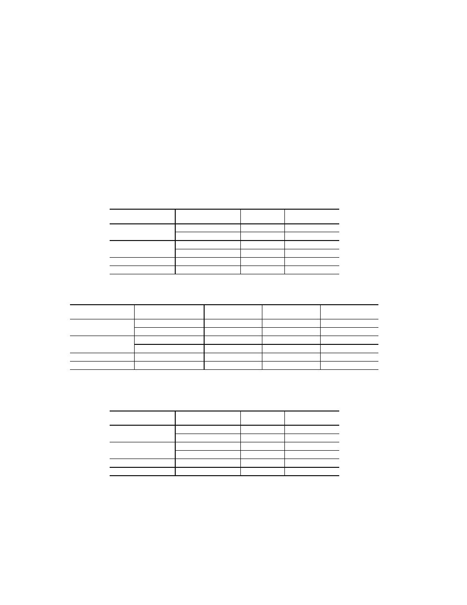
Table 4A — Piston and Charge Combinations — Cooling Only Systems
Table 4B — Piston and Charge Combinations — Heat Pump Systems
*Size 060 indoor heat pump systems use a TXV (thermostatic expansion valve), part no. EA36YD250.
Table 4C — Piston and Charge Combinations — Heat and Cool Systems
*Size 060 indoor heat pump systems use a TXV (thermostatic expansion valve), part no. EA36YD250.
COOLING
INDOOR UNIT SIZE
OUTDOOR UNIT
38HDR
PISTON
SIZE
CHARGE (lb)
024
018
57
7.0
024
57
7.75
036
030
65
10.1
036
70
8.9
048
048
80
12.2
060
060
90
12.5
HEAT PUMP
INDOOR UNIT SIZE
OUTDOOR UNIT
38QRR
PISTON SIZE
INDOOR
PISTON SIZE
OUTDOOR
CHARGE (lb)
024
018
49
40
7.5
024
55
43
7.8
036
030
65
55
12
036
70
63
13
048
048
82
73
12.2
060
060
—*
80
12.8
HEAT PUMP
INDOOR UNIT SIZE
OUTDOOR UNIT
38HDR
PISTON
SIZE
CHARGE (lb)
024
018
57
7.0
024
57
7.75
036
030
65
10.1
036
70
8.9
048
048
80
12.2
060
060
—*
12.5