Step 6 — make electrical connections – Carrier 40QA024-060 User Manual
Page 10
10
Step 6 — Make Electrical Connections —
Be sure
field wiring complies with local building codes and NEC, and
unit voltage is within limits shown in Table 5.
Contact local power company for correction of improper
line voltage.
NOTE: Use copper wire only between disconnect switch(es)
and unit.
NOTE: Install branch circuit disconnect of adequate size to
handle unit starting current per NEC. Locate disconnect within
sight of, and readily accessible from, unit, per Section 440-14
of NEC. Some codes allow indoor unit to share disconnect with
outdoor unit if disconnect can be locked; check local code
before installing in this manner.
1. Route ground and power wires.
2. Route line power leads (see Fig. 16) from indoor dis-
connect to the fan coil unit. Place wire through hole on
the control box (Fig. 17). Connect wire to high voltage
terminal board (TB1) and ground screw. When routing
the wire in the unit, use care to keep the wire away
from refrigerant and condensate piping and any sharp
edges. The 208/230-v units are factory wired for
230-v to 24-v transformer operation. For 208-v to
24-v operation, interchange blue (208-v) and red
(230-v) wires. Cap any unused wires with wire nuts.
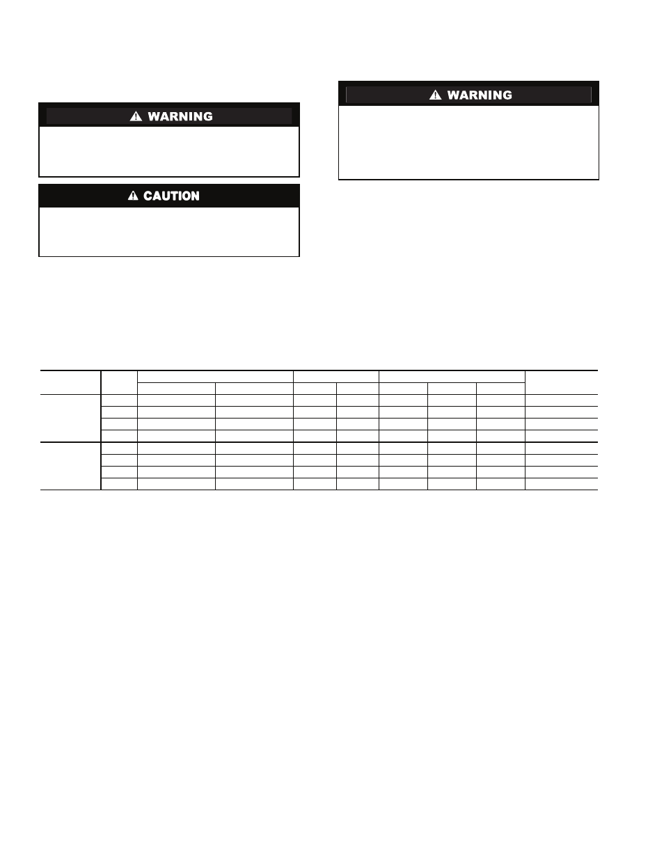
Table 5 — Electrical Data*
LEGEND
*All units are 208/230-1-60. Minimum operating voltage is 187, max-
imum is 253. Units will operate satisfactorily within this voltage
range.
†Electrical data is the same for both the 24,000 Btuh 024 unit and
the 024 unit that has been field-reconfigured for 18,000 Btuh. Refer
to Before Installation section on page 3 for reconfiguration details.
To avoid personal injury or damage to unit, do not make
electrical connections until all power sources are shut
down, locked out, and tagged off. Failure to do so could
result in personal injury or unit damage.
Operation of unit on improper line voltage constitutes abuse
and could affect warranty. Refer to Table 5 for permissible
operating limits. Do not install unit in system where voltage
may fluctuate above or below permissible limits.
According to NEC and most local codes, the unit must have
an uninterrupted, unbroken ground to minimize personal
injury if an electric fault should occur. The ground may
consist of electrical wire or metal conduit when installed in
accordance with existing electrical codes. Failure to follow
this warning could result in an electric shock, fire, or death.
SYSTEM
TYPE
UNIT
SIZE
FAN
HEATER
POWER
MIN WIRE SIZE
(AWG)
Motor 1 FLA
Motor 2 FLA
kW
FLA
MCA
MOCP
FLA
COOLING
ONLY
024†
0.5
—
—
—
0.53
15
0.50
14
036
1.3
—
—
—
1.60
15
1.30
14
048
1.1
0.5
—
—
2.00
15
1.60
14
060
1.3
1.3
—
—
3.30
15
2.60
14
HEAT PUMP
024†
0.5
—
2.00
8.66
9.29
15
9.16
14
036
1.3
—
3.00
13.00
17.70
20
14.30
14
048
1.0
0.5
4.00
17.40
23.80
25
19.00
12
060
1.3
1.3
5.00
21.70
28.70
30
24.30
10
AWG
— American Wire Gage
FLA
— Full Load Amps
MCA
— Minimum Circuit Amps per NEC Section 430-24
MOCP — Maximum Overcurrent Protection
NEC
— National Electrical Code