Tr 11, Assembly instructions – Ryobi 310BVr User Manual
Page 10
Attention! The text in this document has been recognized automatically. To view the original document, you can use the "Original mode".
ASSEMBLY INSTRUCTIONS
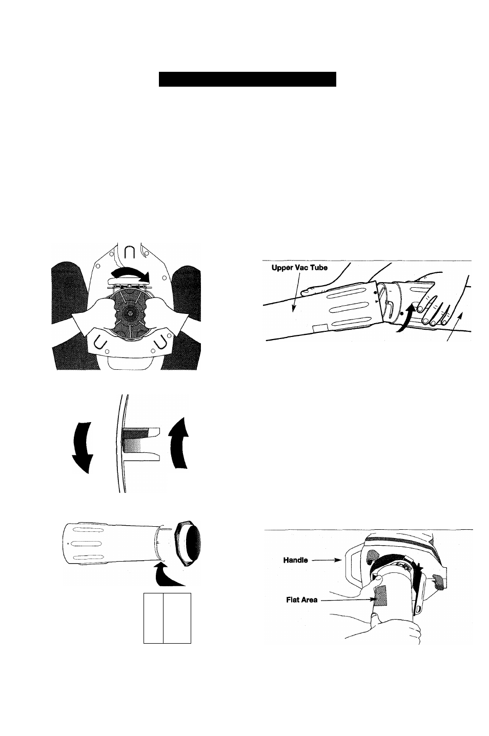
5. Grasping the upper vacuum tube firmly with both hands
(Fig. 9), turn the vacuum tube clockwise (Fig. 10) until
the two (2) tabs of the adapter snap into the two (2)
square indentations of the upper vacuum tube (Fig. 11).
NOTE: This assembly requires the use of both hands
because the parts fit together tightly.
NOTE: The flat area on the upper vacuum tube should face
the handle as you install the vacuum tube (Fig. 13).
NOTE: When the tabs lock into the indentations, the
adapter and vacuum tube become a permanent
assembly. The adapter can no longer be
removed from the vacuum tube.
Fig. 9
Adapter
Fig. 10
t
r
11__
ASSEMBLING THE VACUUM TUBES
(MODEL 310BVr ONLY)
A
WARNING:
Do not install the vacuum tubes
while unit is running to avoid serious
personal injury.
1. Align the arrow on the lower vacuum tube with the
arrow on the upper vacuum tube (Fig. 12).
2. Grasping the lower vacuum tube firmly with both
hands, push the lower vacuum tube into the upper
vacuum tube. Turn the lower vacuum tube clockwise
until it snaps into detent and locks. (The dot on the
lower tube aligns with the dot on the upper tube
when properly assembled.)
Fig. 12
Lower Vac Tube
INSTALLING THE COMPLETE VACUUM TUBE
ASSEMBLY TO THE BLOWER/VACUUM
(MODEL 310BVr ONLY)
A
WARNING:
Do not install the vacuum tubes
while unit is running to avoid serious
personal injury.
1. Grasp the assembled vacuum tube firmly with both
hands. Turn the tube/adapter clockwise as far as
possible to the end of the grooves until It snaps into
the detent and locks (Fig. 13).
NOTE: When the tube is installed correctly, the flat on
the upper tube faces the handle on the
blower/vac (Fig. 13).
Fig. 11
Fig. 13
10