Park f»liig, Service and adjustments, Ne arrangement – Poulan CHDF550D User Manual
Page 13: Tiller, Ro adjust handle height (see fig. 15)
Attention! The text in this document has been recognized automatically. To view the original document, you can use the "Original mode".
Do not op6rat6 tiiter without mufflsr. Do not tampor with
3xhausi system. Damaged mufflers or spark arresters
'iould create a fire hazard. Inspect periodically and replace
f necessary. If your engine is equipped with a spark
rm K* < |•■pм ,} ruth
r'.fr,/ M hoit* i ■>!
!t III 1 ( 'll L 1 t I 111>1 D»j. i
II I
i| i
PARK F»LIIG
epir''€ ..pirr pk 4« Jtdw qciMriqj* j c h i l i n ' a '
c r
!i attcreveiySOhr.umr.timt whitfifc\tn jriieifnD Dpaik
)'uqtypeai‘dyap'etrinq a« -hjwsiin ’^HC'DUt i JFD'I
-Ik Al iOND” on pjqf > nt iti ^ tnanual
- hAr* M i \ ->.1« sN
Your transmissiori is sealed and will not require lubrication
unless serviced.
r; f ^ h m u
• Clean engine, wheels, finish, etc. of ali foreign matter.
'
^ “ p l i r t l h l * i d ^
n | / ‘ f I l i l l M
uli!. eic.
•* f r.it“ > paif>i'd I'd.n ' wrh . -rrmcfive tvf»f wj.
“Zed !
. r r i n m O j I1.4 - 4 M-R
. dfshjfcur
unit unit, .tilt riiufflt r rir filtc 1 anil c jibitw tor irc »rwi-r-ci
ioketpwatcrout Water.rieiigi.i» 1 diiroaUiti la. Iiortt.ied
engine me.
SERVICE AND ADJUSTMENTS
A
CAUTION: Disconnect spark plug wire from spark plug and place wire where it cannot come into
contact with plug.
TILLER
rO ADJUST HANDLE HEIGHT (See Fig. 15)
-actory assembly has provided lowest handle height. Se-
3ct handle height best suited for your tilling conditions,
iandie height will be different when tiller digs into soil.
If a higher handle height is desired, loosen the four nuts
securing handle panel to engine brackets.
Slide handle panel to desired location.
Tighten the four nuts securely.
■|NE ARRANGEMENT
'ouroutertinescan be assembled in several different ways
3 suit your tilling or cultivating needs.
A
CAUTION:
Tines are sharp. Wear
gloves or other protection when han
dling tines.
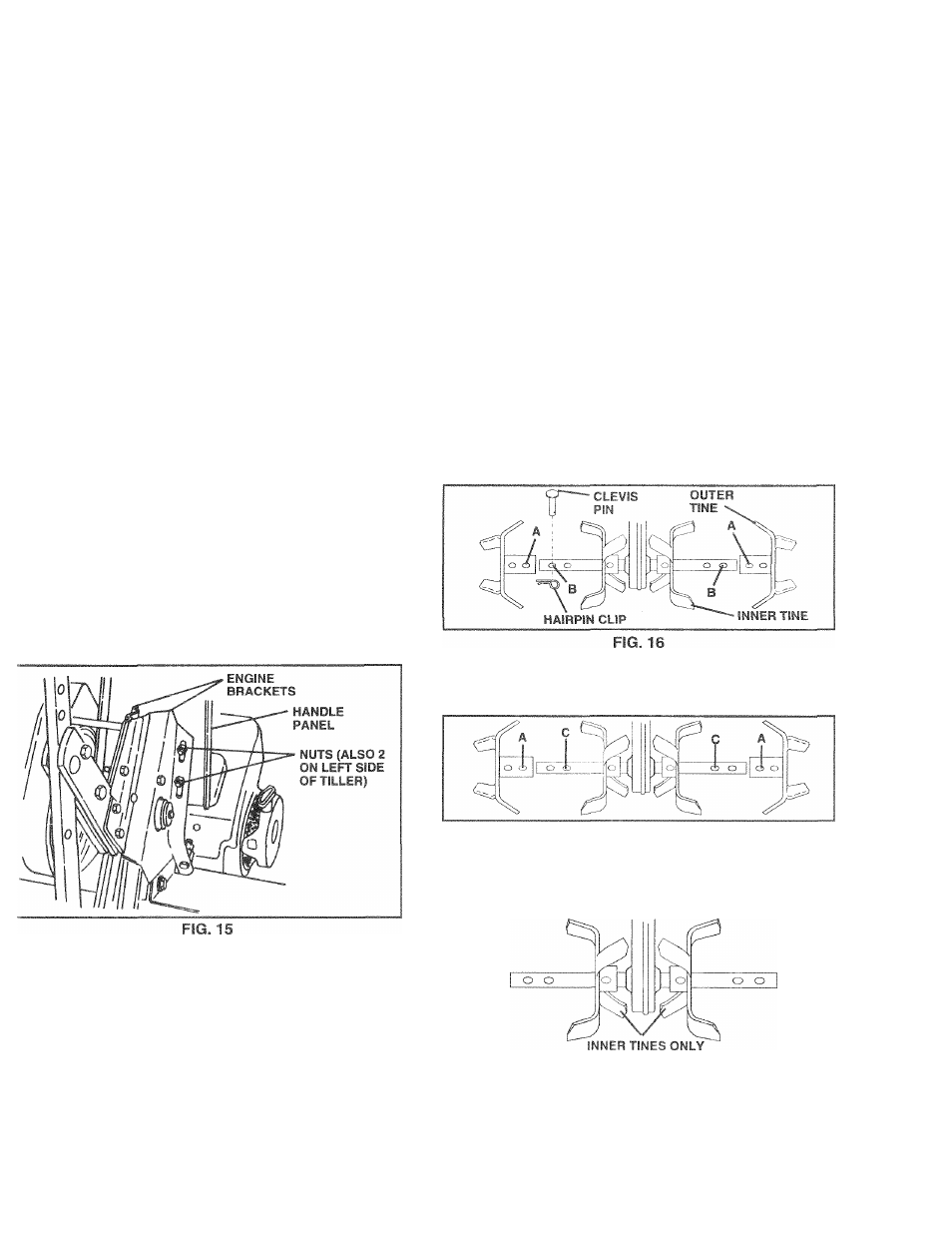
iORMAL TILLING - 26" PATH (See Fig. 16)
Assemble holes “A” in tine hubs to holes “B” in tine
shaft.
MID-WIDTH TILLING - 24" PATH (See Fig. 17)
• Assemble holes “A” in tine hubs to holes “C” in tine
shaft.
FIG. 17
NARROW TILLING/CULTIVATING -12-3/4" PATH (See
Fig.JS)
• Hemove outer tines.
FIG. 18
NOTE: When reassembling outer tines, be sure right tine
assembly (marked “R”) and left tine assembly (marked “L”)
are mounted to correct side of tine shaft.
13