A. getting ready, B. attaching the bar and chain, A getting ready – Poulan 2100 User Manual
Page 7: B. attadungthe bar and chain, Assembly
Attention! The text in this document has been recognized automatically. To view the original document, you can use the "Original mode".
ASSEMBLY
A. GETTING READY
1. READ YOUR OPERATOR’S MANUAL
CAREFUUY
Your Operator’s Manual has been developed to help
you prepare your saw for use and to understand its
safe operation. It is important that you read your
manual completely to become familiar with the
unit before you begin assembly or attempt opera
tion. Your TOULAN dealer is available to showyou
how to operate your saw. Be sure to ask for his as
sistance.
2. HAVE THE FOLLOWING AVAILABLE:
a. Protective gloves.
b. Approved, marked fuel container.
c. One gallon r^rular unleaded gasoline.
d. 2 cycle, air-cooled engine oil (See the “Fueling
Your Engine” section).
e. Bar and Chain Oil (Scte the “Bar and Chain Oil”
section).
f Scrench.
B. ATTACHING THE BAR AND CHAIN
• Your saw is equwped with a Reduced-Eick-
hacfc Bar and a Low-Eickback Chain.
•
Always use the Reduced-Eickback Guide
Bar and Low-£ackhack Chain specxRed for
your chain saw model when replacing these
parts. See the **Speclfications^ section.
A WARNING
Do not start the engine without the guide bar and
chain completely assembled. Otherwise, the
clutch can come oH and serious ixguiy can result.
I
CAUTION; I Wearprotectiv^loves when han
dling or operatingyour saw. The chain is sharp
and can cut you even when it is not moving!
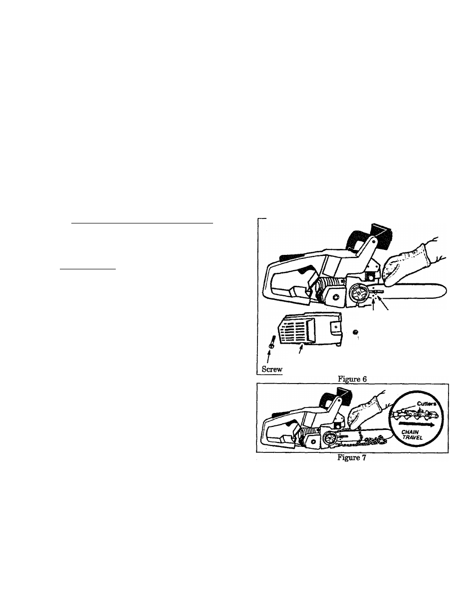
1. Remove the bar clamp nut and screw, bar clamp,
and plastic spacer if you have not already done so.
Discard the plastic spacer.
2. Turn the adjusting screw (Figjm^ 8) counterclock
wise to move the adjusting pin almost as far as it
will go to the rear.
3. Mount the guide bar with the slotted end over the
bar mounting stud. Figure 6. Position the adjust
ing pin in the adjusting pin hole. Figure 6 .
4. Hold the chain with the cutters facing as shown in
Figure 7 (inset),
5. Place the chain over and behind the clutch drum
and onto the sprocket. Figure 7 , Fit the bottom of
the drive links between the teeth in the sprocket.
6. Slide the guide bar toward the rear of the saw as far
as possible.
7. Start at the top of the bar and fit chain drive links
into the groove around the guide bar. Figure 7.
8. Turn the adjusting pin clockwise until the chain is
snug in the guide bar groove. Figure 8 .
9. Hold the guide bar against the saw frame and in
stall the clamp.
10. Replace the bar clamp nut and tighten finger tight
only. Tighten bar damp nut after chain is
tensioned.
11. Replace the screw and tighten securely.
12. Proceed to the “Chain Tension” section.
Bar
Mounting Stud
Adjusting Pin Hole
B
m
-Clamp ' Bar Clamp Nut
NOTES
-
7
-