B. spark arrestor, B. spaik arrestor – Poulan 2100 User Manual
Page 17
Attention! The text in this document has been recognized automatically. To view the original document, you can use the "Original mode".
í
A WARNING
TheDe;
et* dept^
will increase tlie chance of hickback which can
result in serious iidnry*
h. CHAIN REPLACEMENT
1,
) Use only the Low-Kickback replace
ment chain specified for your saw in
the “Specifications” section.
2, ) Replace the chain when cutters or
links break.
3.
) See a qualified service dealer to re
place or sharpen your chain.
4.
) iUways have a worn sprocket replaced
by a qualified service dealer when in
stalling a new chain to avoid excessive
wear to the chain.
2. GUIDE BAR MAINTENANCE
•
Conditions which can require guide bar
maintenance:
— saw cuts to one side.
— saw has to be forced through a cut.
— inadequate supply of oil to bar and
chain.
•
Checkthe condition of the guide bar each
time the chain is shar^ned. A worn guide
bar will damage the chain and make cutting
more difficult.
• Replace the guide bar when:
— the inside groove of guide bar rails is worn,
— the guide bar is bent or cracked. See Fig
ure 32,
• Use only the replacement Reduced-Kick
back Guide Bar specified for your saw in
the “Specification** section.
a. Remove the guide bar to service.
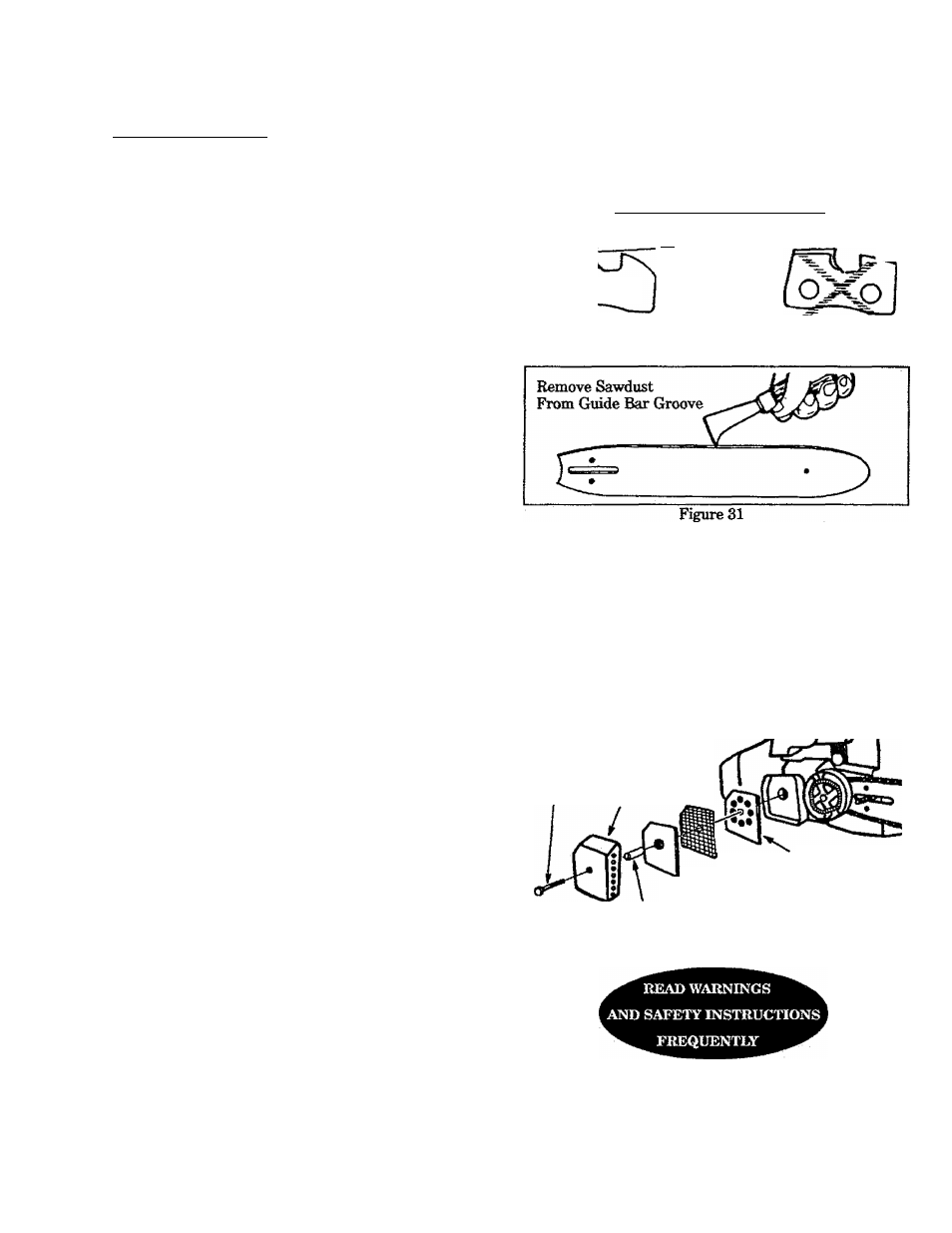
b. Clean the oil holes at least once after every
five hours of operation.
c. Remove sawdust from the pfuide bar groove
periodicallywithaputtyknifeorawire.
Fig
ure 31.
d. Remove burrs by filing the side edges of the
guide bar grooves square with a flat file. Fig-
ure32.
e. Restore square ed^s to an uneven rail top be
filing with a flat file. Figure 32 .__________
Hook^ngie
.025*
^ \
Too Much
Squared
Hook Ande^'"^ Off Comer
o o
Bounded
Comer
Right Way
Wrong Way
Figure 30
Correct
Guide Bar
Groove
Worn Grooves
File Edges
Square
Figure 32
B. SPARK ARRESTOR
•
Carbon deposits build up on the spark arres
tor as the sawis used and must be removed to avoid
creating a fire hazard or causing engine damage.
• Replace the spark arrestor if breaks occur.
• Keep the spark arrestor clean at all. times.
Clean:
—as required.
—at least once for each 25-30
hours of operation.
Items required: wire brush, 3/8” wrench
1. Disconnect the spark plug wire.
2. Remove the muffler cover screw. Remove the
muffler cover. Figure 33 .
3. Remove the spark arrestor screen. Figure 33 .
4. Clean the screen with a wire brush or replace if
breaks are found.
5. Reassemble parts.
Muffler
Cover
Muffler
Screw Coyer
N
Spacer Baffle Plate
Baffle Plate
Spark Arrestor Screen
Figure 33
-
17
-